onlinecomponents.com
INTERBUS Loop
6057AC01 1-19
1.7.2 Mounting a BK Module With IP 65/IP 67
Protection
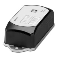
BK modules with IP 65/IP 67 protection are installed directly on an even
mounting surface.
The mounting surface must be flat to avoid strain in the housing when
tightening the screws.
Grounding When mounting the module directly, the module is grounded with the lower
mounting screw. Make sure that the mounting angle or mounting plate is
grounded.
Additional
grounding
The M4 bore hole on the left housing side panel (sectional view A-A in
Figure 1-10 on page 1-15) is provided for an additional FE connection.
Mounting • Mount the module with the two M4 hexagonal socket-head screws that
are part of the housing.
1.7.3 Mounting INTERBUS Loop Modules
The INTERBUS Loop modules with IP 65/IP 67 protection can be:
– Mounted on aluminum profiles or
– Mounted directly onto a flat mounting surface.
The mounting surface must be flat to avoid strain in the housing when
tightening the screws.
Grounding When mounting the module directly, the module is grounded with the lower
mounting screw. Make sure that the mounting angle or mounting plate is
grounded.
Mounting position The INTERBUS Loop modules can be mounted in any position.
Mounting • You can directly mount the modules on the mounting surface, or on
mounting profiles, through 2 mounting holes (
« 4 mm [0.157 in.],
cylindrical sinking 8 mm [0.315 in.]).
The drill hole distance in vertical direction is 114.7 mm (4.516 in.) or
84.7 mm (3.35 in.) or 54.7 mm (2.154 in.) (see Figure 1-11 on page 1-16 to
Figure 1-13 on page 1-17).

 Loading...


