Installation
Installation Manual PNOZmulti Installation Manual
1002265-EN-02
22
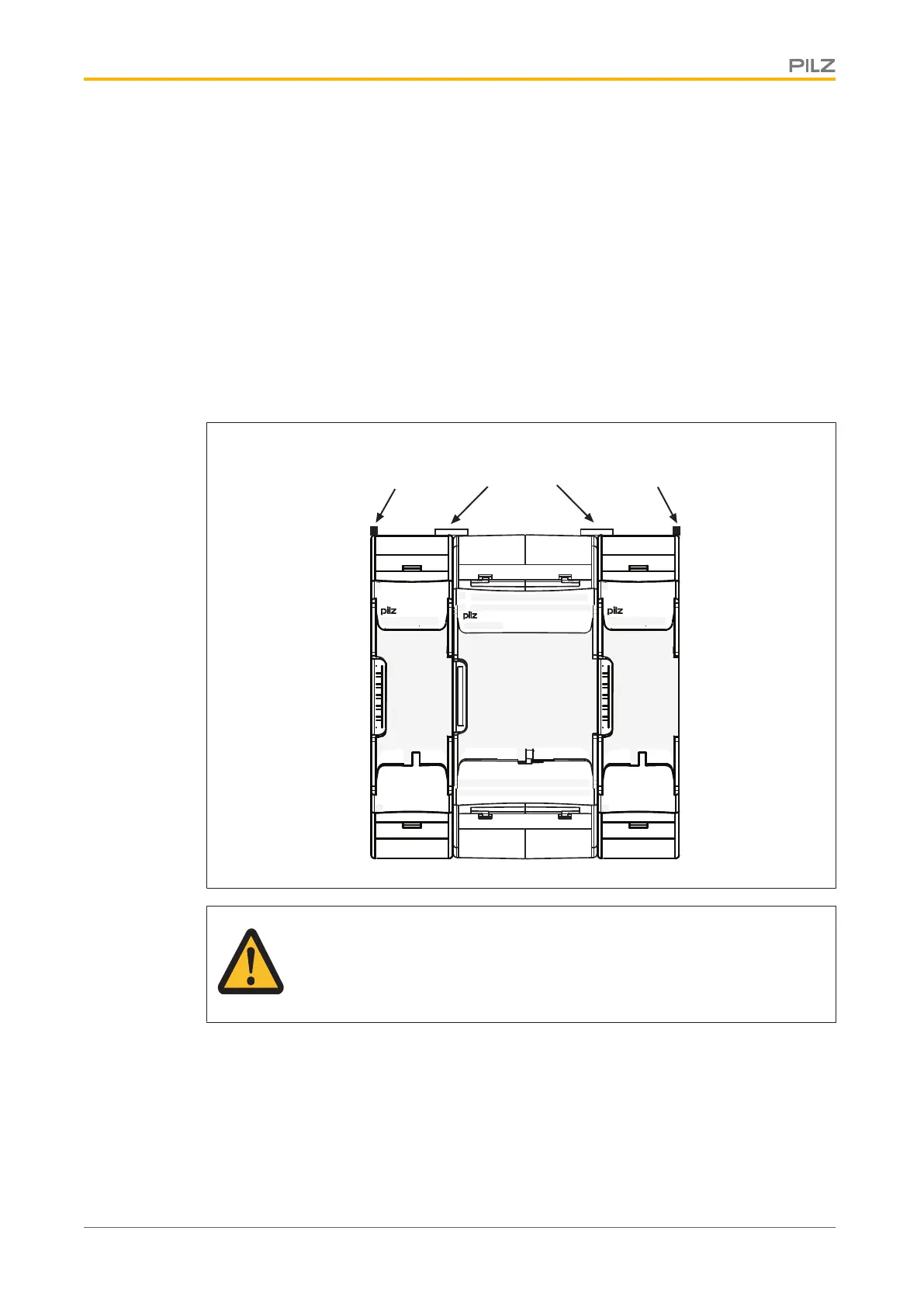
4.4.2 Connecting the base unit and expansion modules
The position of the expansion modules is defined in the PNOZmulti Configurator. The ex-
pansion modules are connected to the left or right of the base unit, depending on the type.
Please refer to the document "PNOZmulti System Expansion" for details of the number of
modules that can be connected to the base unit and the module types.
The modules are linked via jumpers.
} Remove the terminator on the side of the base unit and on the expansion module.
} Install the base unit and expansion modules on the mounting rail in the order configured
in the PNOZmulti Configurator and connect the units using the jumper supplied.
} Fit the terminator to the unconnected interfaces on the base unit and expansion mod-
ule.
Terminator Terminator
IM0
IM1
IM2 I6
I5
I4IM3 I7
I8
I10 I14
I13
I12I11 I15
X3
X1
X4
X2
PNOZ mm0.1p
T0
T1
T2 O2
O1
O0T3 O3
IM16
IM17
IM18 0 V
A2
A1IM19 24 V
M20
M21
M22 M23
Jumper
CAUTION!
Only connect the base unit and expansion modules when the supply voltage
is switched off.
 Loading...