Connecting the Control System PNOZmulti
Installation Manual PNOZmulti Installation Manual
1002265-EN-02
24
5.3 Earthing
When units from the configurable control system PNOZmulti are attached to the mounting
rail, earthing springs establish the electrical contact between the units' functional earth and
the mounting rail. There is no earthing spring on the PNOZmulti Mini. Any connection re-
quired to the mounting rail must be established externally (e.g. with the link modules
PNOZmml1p, PNOZmml2p).
} Always connect the mounting rail to the protective earth via an earthing terminal. This
will be used to dissipate hazardous voltages in the case of a fault.
The mounting rail must be properly earthed to ensure interference-free operation in accord-
ance with EMC regulations.
INFORMATION
Please refer also to the earthing information provided in the chapter entitled
"Electromagnetic Compatibility", under "Connecting the earth cables".
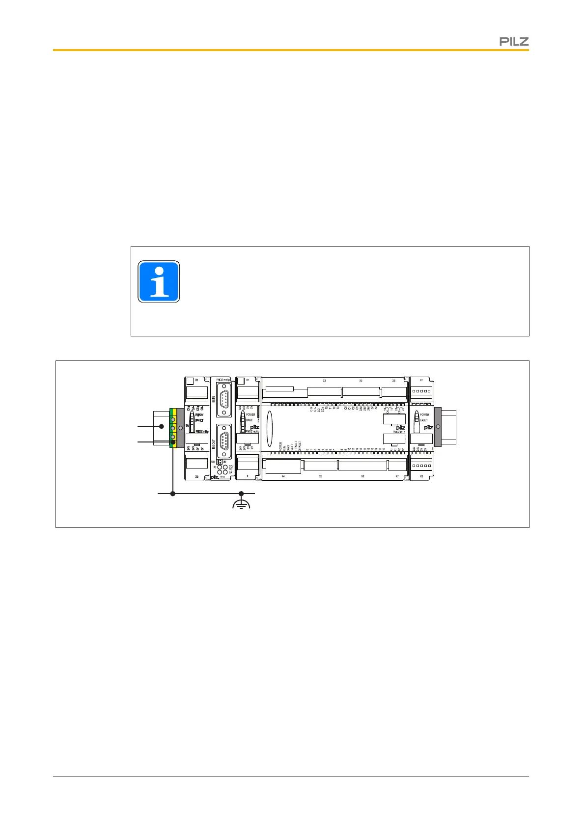
Earthing the mounting rail
CHIP-Card
PNOZ mo3p
O1+
O0-
O0+
O1-
2
Shield
1
2
Key:
} 1: Mounting rail
} 2: Earthing terminal
5.4 Cable requirements
Configurable safety systems PNOZmulti
Screw terminals:
} The minimum cable cross section on field connection terminals is 0.5 mm
2
(AWG22)
} The maximum cable cross section on field connection terminals is
– Digital inputs: 1.5 mm
2
(AWG16)
– Digital outputs: 1.5 mm
2
(AWG16)
– Relay outputs: 2.5 mm
2
(AWG12)
– Analogue inputs: 1.5 mm
2
(AWG16)
 Loading...