Connecting the Control System PNOZmulti
Installation Manual PNOZmulti Installation Manual
1002265-EN-02
26
} Evaluation of an output's feedback loop
} Test pulses for detecting shorts between contacts on inputs
Wiring guidelines and connection examples are available in the operating manuals or data
sheets for the input/output modules.
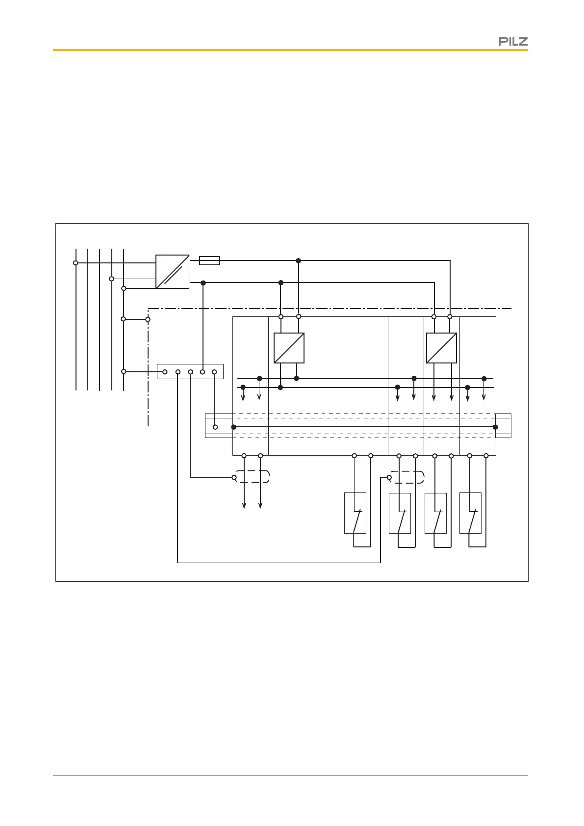
5.7 Example of EMC-compliant wiring
The following example illustrates an EMC-compliant connection for a configurable control
system PNOZmulti (e.g. PNOZm1p with expansion modules).
=
=
=
~
L1 L2 L3 N PE
TN-S
Control cabinet
Earthing
bar
Mounting rail
+ 5 V DC
0 V
+ 24 V DC
0 V
Functional earth
Periphery
-Sensors
-Actuators
Fieldbus
PNOZmulti
=
=
5.8 Analogue input module
Note:
} Use shielded, twisted pair cable for the connections on the input current circuits.
} Separate the supply voltage cable from the analogue input current lines.
} For transducers located outside the control cabinet: Where the cable enters the control
cabinet, the cable shield must be connected to the earth potential over a wide surface
area and with low impedance (connect in star).
 Loading...