Connecting the Control System PNOZmulti
Installation Manual PNOZmulti Installation Manual
1002265-EN-02
27
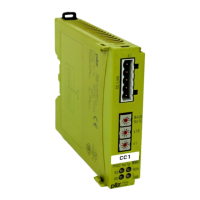
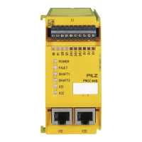
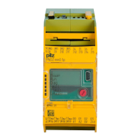
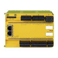
5.9 Motion monitoring modules
Connection technology
} Proximity switch
Plug-in connection terminals (either cage clamp terminals or screw terminals)
} Encoder
– Mini-IO socket with motion monitoring modules PNOZ m EF XMM
– RJ45 socket with speed monitors PNOZ msXp for configurable safety systems
PNOZmulti
Please note the following when connecting the encoder:
} The adapter cable should be as short as possible.
} A shielded connection box should be used for the sensor signals
} A separate power supply, isolated from the drive, should be used to supply voltage to
the sensors.
INFORMATION
The following applies for the speed monitor PNOZ msXp with RJ45 connec-
tion:
The shield connection for the incremental encoder is established via the
RJ45 connector housing. Use ready-made cable from Pilz (see units' oper-
ating manuals and Technical Catalogue).
INFORMATION
The following applies for motion monitoring modules with Mini-IO connec-
tion:
The shield connection for the encoder is established via the adapter cable
housing on the drive / inverter.
If necessary, the shielding braid on the adapter cable can be connected to
the functional earth via a shield clamp on the mounting rail.
Use ready-made cable from Pilz (see units' operating manuals and Tech-
nical Catalogue).
 Loading...