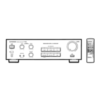
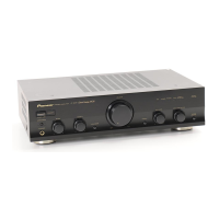
A-307R, A-207R
26
No. Pin name I/O Function
24 P51/XCOUT I SPEAKER-A KEY input.
25
RESET
I Reset pin.
26 P30/INT0 I BACK UP detection pin. interrupt specification.
27 P31/INT1 I Not used.
28 P32/CNTR0 I REC selector input 1.
29 P33/CNTR1 I REC selector input 2. interrupt specification.
30 P40 O Volume DOWN data output.
31 P41 O Volume UP data output.
32 P42 I FUNCTION selector input 1.
33 P43 I FUNCTION selector input 2.
34 P0
0 I
WAKE UP input.
Key on wake up specification.
35 P01 O Not used.
36 P0
2 I
DIRECT KEY input.
Key on wake up specification.
37 P03 O Protection control pin.
38 P04 I Output error detection pin
39 P05 O MUTING control pin.
40 P0
6 I
LOUDNESS KEY input.
Key on wake up specification.
41 P07 O Not used.
42 P5
2 I TAPE2 KEY input.
No. Pin name I/O Function
1P53 I Remote control signal input pin.
2
P1
7/SRDY
O STB for TC9163N.
3P16/CLK O CLOCK for TC9163N.
4P15/SOUT O DATA for TC9163N.
5P14/SIN O CD INDICATOR.
6P13/T1 O TUNER INDICATOR.
7P12/T0 O PHONO INDICATOR.
8P11 O LINE INDICATOR.
9P10 O TAPE1 INDICATOR.
10 P27/IN7 O SPEAKER-A INDICATOR.
11 P26/IN6 O SPEAKER-B INDICATOR.
12 P25/IN5 O LOUDNESS INDICATOR.
13 P24/IN4 O Not used.
14 P23/IN3 O Not used.
15 P22/IN2 O DIRECT INDICATOR.
16 P21/IN1 O TAPE2 INDICATOR.
17 P20/IN0 O FUNCTION switch MUTE.
18 VREF I Pulls up to 5V.
19 XIN I 4.19MHz .
20 XOUT O Ceramic vibrating and connecting terminal.
21 VSS - Digatal GND.
22 VCC - Power supply +5V.
23 P5
0/XCIN I SPEAKER-B KEY input.
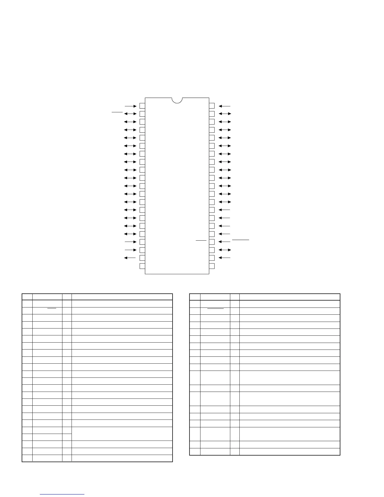
7. GENERAL INFORMATION
7.1 IC
7 PD5443A (FRONT R ASSY : IC601)
REMOTE CONTROL AMP MICROCOMPUTER
¶ Pin Assignment (Top view)
• The information shown in the list is basic information and
may not correspond exactly to that shown in the schematic
diagrams.
¶ Pin Function
1
2
3
4
5
6
7
8
9
10
11
12
13
14
15
16
17
18
19
20
21
22
23
24
25
26
27
28
29
30
31
32
33
34
35
36
37
38
39
40
41
42
SR
STB
CLK
DATA
CD-IND
TU-IND
PH-IND
LI-IND
T1-IND
SPA-IND
SPB-IND
LOU-IND
NC
NC
DIR-IND
T2-IND
V
REF
X
IN
X
OUT
V
SS
F-MUTE
P5
3
P1
7
/S
RDY
P1
6
/CLK
P1
5
/S
OUT
P1
4
/S
N
P1
3
/T
1
P1
2
/T
0
P1
1
P1
0
P2
7
/IN
7
P2
6
/IN
6
P2
5
/IN
5
P2
4
/IN
4
P2
3
/IN
3
P2
2
/IN
2
P2
1
/IN
1
P2
0
/IN
0
V
REF
X
N
X
OUT
V
SS
T2
NC
LOUD
M-CTRL
P-DET
P-CTRL
DIRECT
NC
WAKE UP
FUNC2
FUNC1
V-UP
V-DOWN
RSEL2
RSEL1
NC
V
CC
P5
2
P0
7
P0
6
P0
5
P0
4
P0
3
P0
2
P0
1
P0
0
P4
3
P4
2
P4
1
P4
0
P3
3
/CNTR
1
P3
2
/CNTR
0
P3
1
/INT
1
P3
0
/INT
0
RESET
P5
1
/X
COUT
P5
0
/X
CIN
V
CC
BACK UP
RST
SPA
SPB