
E
elizabeth25Jul 31, 2025
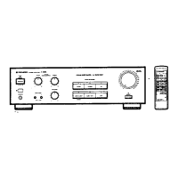
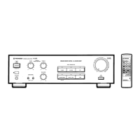
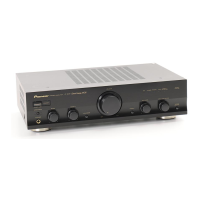
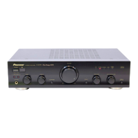
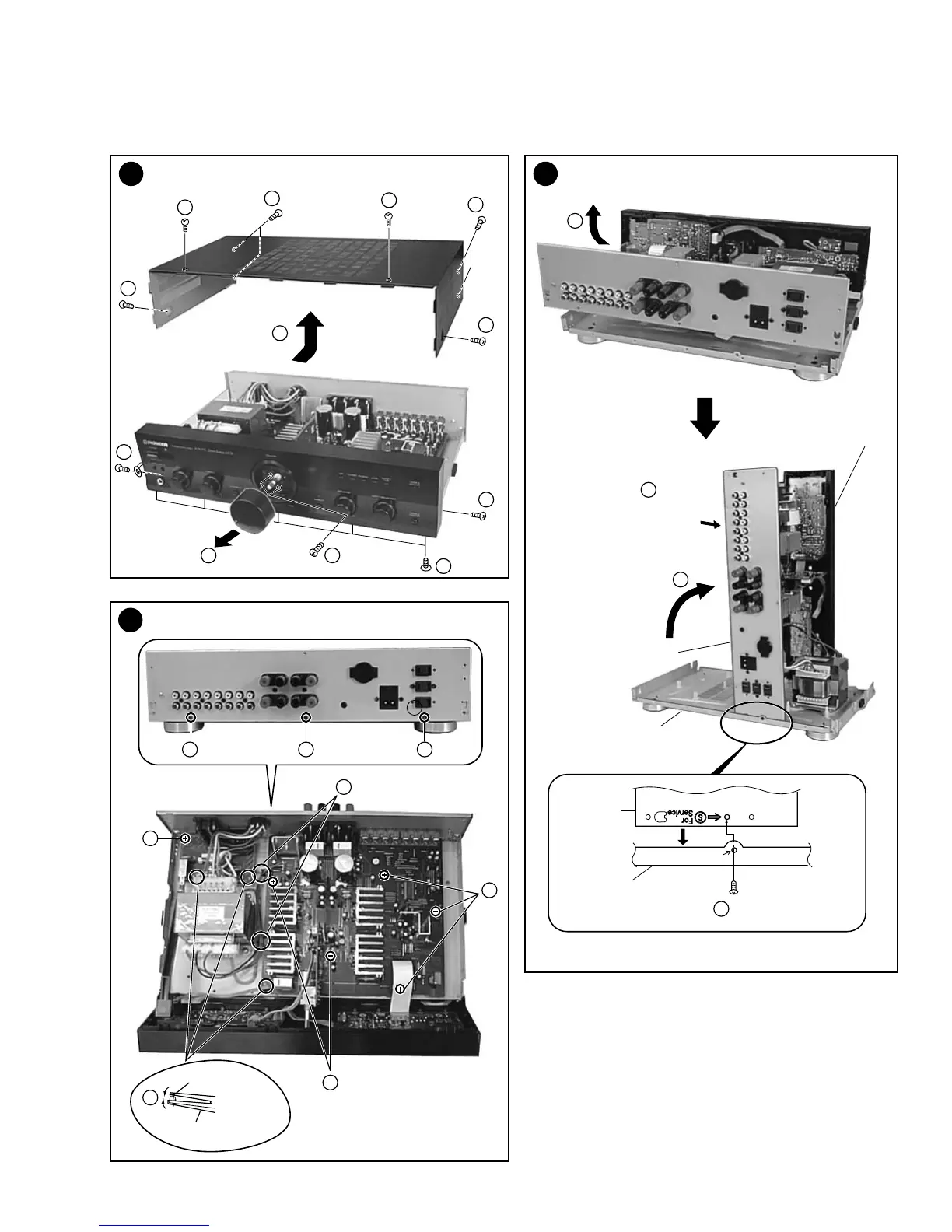
Why is my Pioneer A-307R Amplifier not turning on?
- Ddaniel28Jul 31, 2025
If your Pioneer Amplifier isn't getting power, first ensure the power plug is securely inserted into the outlet. Also, check if the amplifier is plugged into another component's power outlet (like a timer) and that the other component is powered on. Finally, make sure the AC INLET plug is fully inserted into the jack.