29
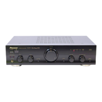
A-307R, A-207R
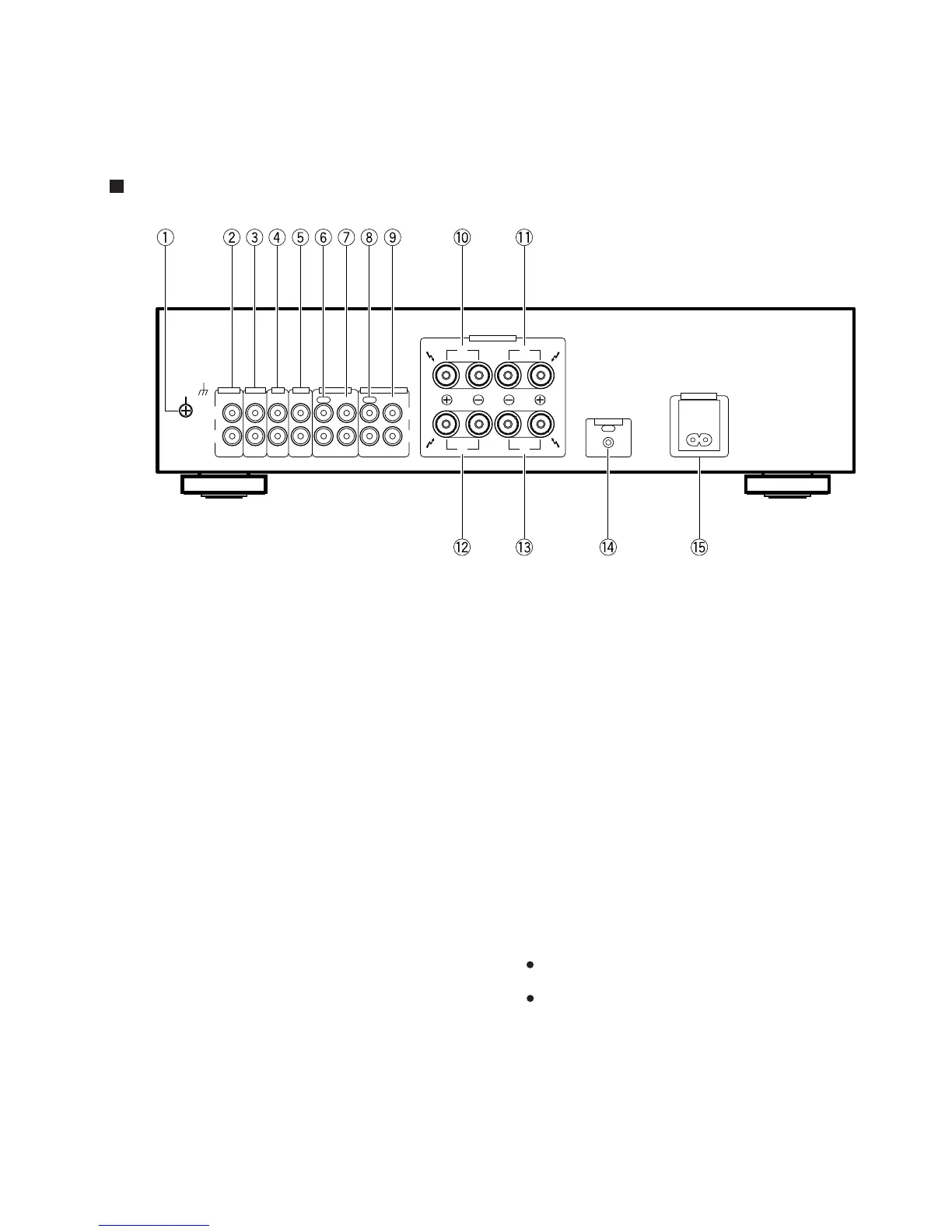
REAR PANEL
1 GND (Turntable ground) terminal
2 PHONO terminals
3 TUNER terminals
4 CD terminals
5 LINE terminals
6 TAPE 1/MD REC (OUT) terminals
7 TAPE 1/MD PLAY (IN) terminals
8 TAPE 2 MONITOR REC (OUT) terminals
9 TAPE 2 MONITOR PLAY (IN) terminals
0 SPEAKERS B terminals (Right channel)
- SPEAKERS B terminals (Left channel)
= SPEAKERS A terminals (Right channel)
~ SPEAKERS A terminals (Left channel)
! CONTROL OUT jack
This jack is for output of control signals when operating other
components bearing the Î mark with the attached remote
control unit.
@ AC INLET jack
Connect power cord to here and an AC wall socket, or the AC
outlet of an audio timer.
If you are going to be away from home for a long period of time,
disconnect the unit from the wall socket.
NOTES:
If you use an other power cord than provided, we cannot
assume the liabilities in what may occur as a result of it.
(The provided power cord has a current capacity of 2.5 A.)
A
L
R
T TA M
A A
A 2 M
TT
L
R
SPEAKERS
AC INLE
T
T
RL
R
A
B
L
8. PANEL FACILITIES AND SPECIFICATIONS
8.1 PANEL FACILITIES
 Loading...