33
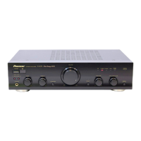
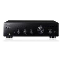
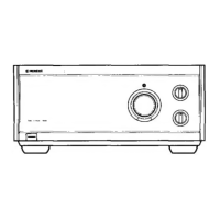
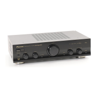
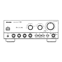
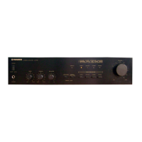
A-307R, A-207R
Amplifier Section
Continuous power output
(both channels driven at 20 Hz to 20 kHz)∗∗
[A-307R]
T.H.D. 0.1 %, 8 Ω ..................................... 45 W + 45 W∗
T.H.D. 0.15 %, 4 Ω ................................... 65 W + 65 W∗
[A-207R]
T.H.D. 0.1 %, 8 Ω ..................................... 35 W + 35 W∗
T.H.D. 0.15 %, 4 Ω ................................... 45 W + 45 W∗
DIN Continuous power output
(both channels driven at 1 kHz)
[A-307R]
T.H.D. 1.0 %, 8 Ω ...................................... 55 W + 55 W
T.H.D. 1.0 %, 4 Ω ...................................... 80 W + 80 W
[A-207R]
T.H.D. 1.0 %, 8 Ω ...................................... 45 W + 45 W
T.H.D. 1.0 %, 4 Ω ...................................... 60 W + 60 W
Total harmonic distortion∗∗
[A-307R]
20 Hz to 20 kHz, 22.5 W, 8 Ω ............................ 0.08 %∗
[A-207R]
20 Hz to 20 kHz, 17.5 W, 8 Ω ............................ 0.08 %∗
÷ Power output specification is for when power supply is
230V.
Input sensitivity/impedance
PHONO (MM) ........................................... 2.8 mV/50 kΩ
CD, TUNER, LINE, TAPE 1/MD, TAPE 2 MONITOR
.................................................................. 200 mV/50 kΩ
PHONO (MM) overload level
1 kHz, T.H.D. 0.1 % ............................................ 150 mV
Output level/impedance
TAPE 1 REC, TAPE 2 MONITOR REC..... 200 mV/1 kΩ
Frequency response
PHONO (MM) ......................... 20 Hz to 20 kHz, ±0.5 dB
CD, TUNER, LINE, TAPE 1/MD, TAPE 2 MONITOR
.................................................... 5 Hz to 100 kHz,
+0
–3
dB∗
Tone control
BASS ....................................................... ±8 dB (100 Hz)
TREBLE................................................... ±8 dB (10 kHz)
Loudness contour (volume control set at –30 dB position)
........................................ +6 dB (100 Hz)/+4 dB (10 kHz)
Signal-to-Noise ratio (IHF short circuit, A network)
PHONO (MM, 5 mV input) ................................... 85 dB∗
CD, TUNER, LINE, TAPE 1/MD, TAPE 2 MONITOR
............................................................................ 106 dB∗
Signal-to-Noise ratio (DIN, continuous power/50 mW)
PHONO (MM) .............................................71 dB/67 dB∗
CD, TUNER, LINE, TAPE 1/MD, TAPE 2 MONITOR
................................................................... 91 dB/71 dB∗
Power Supply/Miscellaneous
Power requirements ................... AC 220 – 230 V, 50/60 Hz
Power consumption
[A-307R] ................................................................ 140 W
[A-207R] ................................................................ 130 W
Dimensions (including knobs and other protruding parts)
...................................... 420 (W) x 114 (H) x 307 (D) mm
Weight (without package)
[A-307R] .................................................................5.9 kg
[A-207R] .................................................................4.7 kg
Accessories
Remote control unit ............................................................. 1
Batteries (AA/R6P).............................................................. 2
Power cord (Rated current 2.5 A) ....................................... 1
Operating instructions ......................................................... 1
Warranty card ..................................................................... 1
NOTE:
Specifications and design are subject to possible modifica-
tions without notice, due to improvements.
∗ Measured with DIRECT button set to on.
∗∗ Measured by Audio Spectrum Analyzer.
8.2 SPECIFICATIONS