DJM-500
4. SCHEMATIC AND PCB CONNECTION DIAGRAMS
NOTE FOR SCHEMATIC DIAGRAMS Type 2A
1. When ordering service parts, be sure to refer to
"PARTS LIST of EXPLODED VIEWS" or "PCB
PARTS LIST".
2. Since these are basic circuits, some parts of them or the
values of some components may be changed for improve-
ment.
3. RESISTORS:
Unit: k:kQ, M:MQ, or Q unless otherwise noted,
Rated power: 1/4W, 1/6W, 1/8W, 1/10W unless otherwise
noted,
Tolerance: (F): :11%, (G): :12%, (K): :110%, (M): :120% or :15% un-
less otherwise noted,
4. CAPACITORS:
Unit: p:pF or !1F unless otherwise noted,
Ratings: capacitor (!1F)/ voltage (V) unless otherwise noted,
Rated voltage: 50V except for electrolytic capacitors,
5. COILS:
Unit: m:mH or !1H unless otherwise noted,
6. ,VOLTAGE AND CURRENT:
L: or - V:
The -14dBV (1kHz) signal on the CH1 (LINE) side is
shown by the DC voltage (V) at the time of input.
~ mA or - mA:
DC current at no input signal unless otherwise noted,
7. OTHERS:
. ø or 0 : Adjusting point.
. .. : Measurement point.
. The & mark found on some component parts indicates the im-
portance of the safety factor of the parts. Therefore, when re-
placing, be sure to use parts of identical designation,
8, SCH-O ON THE SCHEMATIC DIAGRAM:
· SCH-O indicates the drawing number of the schematic dia-
gram, (SCH stands for schematic diagram,)
9. SWITCHES (Underline indicates switch position):
EFFECT VR ASSY
S171: CH, SELECTOR (1-~-3-4-MIC)
S174: EFFECT SELECTOR
(AUTO BPM-DELAY-ECHO-AUTO PAN
-FLANGER-REVERB-PITCH-SEND RETURN)
VR ASSY
S1:
S2:
S281:
S282:
S283:
S284:
S285:
S401:
S402:
S403:
S404:
MASTER STEREO-MONO
MONITOR STEREO-MONO
FADER START (CH1) ON-OFF
ASSIGN A 1 - 2 - 3 - 4
ASSIGN B 1-2-3-4
CROSS FAD-ER ON - OFF
FADER START (CH2) ON-QFF
INPUT SELECTOR (CH1) CD1-L1NE1
INPUT SELECTOR (CH2) CD2-PHON01
INPUT SELECTOR (CH3) L1NE3-PHON02
INPUT SELECTOR (CH4) SUBMIC-PHON03
7SEG, ASSY
S652: MONITOR SELECTOR EFFECT
S653: MONITOR SELECTOR MASTER
S654: MONITOR SELECTOR CH4
S657: MONITOR SELECTOR MIC
S658: MONITOR SELECTOR CH1
S659: MONITOR SELECTOR CH2
S660: MONITOR SELECTOR CH3
S665: BPM REAL TIME-AVERAGE
VOLTAGE SELECT ASSY
S902: VOLTAGE SELECTOR AC11 0-120V/220-240V
POWER SW ASSY
S901: POWER SW ON-OFF
10
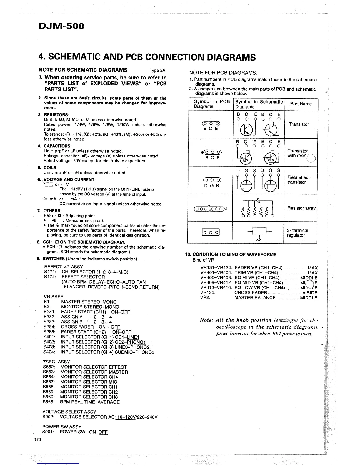
NOTE FOR PCB DIAGRAMS:
1. Part numbers in PCB diagrams match those in the schematic
diagrams.
2, A comparison between the main parts of PCB and schematic
diagrams is shown below,
Symbol in PCB
Symbol in Schematic
Part Name
Diagrams
Diagrams
B C E
B C E
~
~
~
Transistor
B C E
,
B
C
E
B
C E
~
~ ~
Transistor
B C E
with resisr-")
""-~"./
D
G S
D G S
(00 0)
tt
tå
Field effect
transistor
D G S
(000%000):
mm
Resistor array
~
n
3- terminal
regulator
,
10. CONDITION TO BIND OF WAVEFORMS
Bind ofVR
VR131-VR134: FADER VR (CH1-GH4) ..,....,..,....... MAX
VR401-VR404: TRIM VR (CH1-CH4) '.........,....,...... MAX
VR405-VR408: EO HI VR (CH1-CH4) ...........,.., MI LE
VR409-VR412: EO MID VR (CH1-GH4) ..,....,.... M E
VR413-VR416: EO LOW VR (CH1-CH4) .........., MI E
VR135: CROSS FADER ....,......,.............., A SIDE
VR2: MASTER BALANCE ..,.........,...., MIDDLE
Note: All the knob position (settings) for the
oscilloscope in the schematic diagrams
procedures are for when 10:1 probe is used,
 Loading...