4
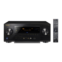
VSX-821-K
1
2 3 4
A
B
C
D
E
F
1
2 3 4
CONTENTS
SAFETY INFORMATION ..........................................................................................................................................................2
1. SERVICE PRECAUTIONS ....................................................................................................................................................5
1.1 NOTES ON SOLDERING ...............................................................................................................................................5
1.2 SERVICE NOTICE ..........................................................................................................................................................5
2. SPECIFICATIONS .................................................................................................................................................................6
3. BASIC ITEMS FOR SERVICE...............................................................................................................................................9
3.1 CHECK POINTS AFTER SERVICING............................................................................................................................9
3.2 JIGS LIST........................................................................................................................................................................9
3.3 PCB LOCATIONS .........................................................................................................................................................10
4. BLOCK DIAGRAM...............................................................................................................................................................14
4.1 OVERALL WIRING DIAGRAM......................................................................................................................................14
4.2 AUDIO BLOCK DIAGRAM (for VSX-821-K, VSX-521-K)..............................................................................................16
4.3 AUDIO BLOCK DIAGRAM (for VSX-921-K)..................................................................................................................18
4.4 D-MAIN BLOCK DIAGRAM (for VSX-821-K, VSX-521-K) ............................................................................................20
4.5 D-MAIN BLOCK DIAGRAM (for VSX-921-K) ................................................................................................................22
4.6 VIDEO BLOCK DIAGRAM ............................................................................................................................................24
4.7 POWER SUPPLY and MAIN UCOM BLOCK DIAGRAM ..............................................................................................26
5. DIAGNOSIS.........................................................................................................................................................................28
5.1 TROUBLESHOOTING ..................................................................................................................................................28
5.2 ADAPTER ERROR MESSAGE.....................................................................................................................................44
5.3 USB / iPod ERROR MESSAGE ....................................................................................................................................45
5.
4 DETECTION CIRCUIT..................................................................................................................................................46
6. SERVICE MODE .................................................................................................................................................................48
6.1 SERVICE MODE...........................................................................................................................................................48
7. DISASSEMBLY....................................................................................................................................................................52
8. EACH SETTING AND ADJUSTMENT ................................................................................................................................62
8.1 ADJUSTMENT REQUIRED WHEN THE UNIT IS REPAIRED OR REPLACED ..........................................................62
8.2 UPDATING OF THE FIRMWARE..................................................................................................................................63
8.3 IDLE CURRENT ADJUSTMENT ..................................................................................................................................67
9. EXPLODED VIEWS AND PARTS LIST...............................................................................................................................70
9.1 PACKING SECTION......................................................................................................................................................70
10. SCHEMATIC DIAGRAM ....................................................................................................................................................80
10.1 AUDIO ASSY ..............................................................................................................................................................80
10.2 AMP ASSY (1/2) (for VSX-921-K) ...............................................................................................................................82
10.3 AMP ASSY (2/2) (for VSX-921-K) ...............................................................................................................................84
10.4 AMP ASSY (1/2) (for VSX-821-K, VSX-521-K) ...........................................................................................................86
10.5 AMP ASSY (2/2) (for VSX-821-K, VSX-521-K) ...........................................................................................................88
10.6 M
AIN ASSY.................................................................................................................................................................90
10.7 SUBWOOFER, HEADPHONE, MIC, GUIDE L, R, WIRE GUIDE A and B ASSYS....................................................92
10.8 VIDEO ASSY ..............................................................................................................................................................94
10.9 F-VIDEO, FRONT and POWER ASSYS .....................................................................................................................96
10.10 CPU, BRIDGE A and B ASSYS ................................................................................................................................98
10.11 STANDBY ASSY .....................................................................................................................................................100
10.12 D-MAIN ASSY (1/4) ................................................................................................................................................102
10.13 D-MAIN ASSY (2/4) ................................................................................................................................................104
10.14 D-MAIN ASSY (3/4) ................................................................................................................................................106
10.15 D-MAIN ASSY (4/4) ................................................................................................................................................108
10.16 USB ASSY (VSX-821-K, VSX-921-K only) .............................................................................................................110
10.17 BT ASSY .................................................................................................................................................................112
11.
PCB CONNECTION DIAGRAM ......................................................................................................................................114
11.1 AUDIO ASSY ............................................................................................................................................................114
11.2 AMP ASSY (for VSX-921-K) .....................................................................................................................................116
11.3 AMP ASSY (for VSX-821-K, VSX-521-K) .................................................................................................................118
11.4 MAIN ASSY...............................................................................................................................................................120
11.5 SUBWOOFER, HEADPHONE and MIC ASSYS ......................................................................................................124
11.6 GUIDE L, R, WIRE GUIDE A and B ASSYS.............................................................................................................126
11.7 VIDEO ASSY ............................................................................................................................................................128
11.8 F-VIDEO, FRONT and POWER ASSYS...................................................................................................................130
11.9 CPU ASSY ................................................................................................................................................................134
11.10 BRIDGE A and B ASSYS........................................................................................................................................138
11.11 STANDBY ASSY .....................................................................................................................................................139
11.12 D-MAIN ASSY.........................................................................................................................................................140
11.13 USB A
SSY (VSX-821-K, VSX-921-K only) .............................................................................................................144
11.14 BT ASSY .................................................................................................................................................................145
12. PCB PARTS LIST ............................................................................................................................................................146
 Loading...