(5) Remove the four screws. (BBZ30P080FTC)
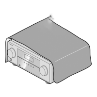
(6) Arrange the unit as shown in the photo below.
(7) Connect the chassis ground.
See “2. Notes on Ground Points Connection”.
5 5 5
5
6
7
MAIN Assy
MAIN Assy
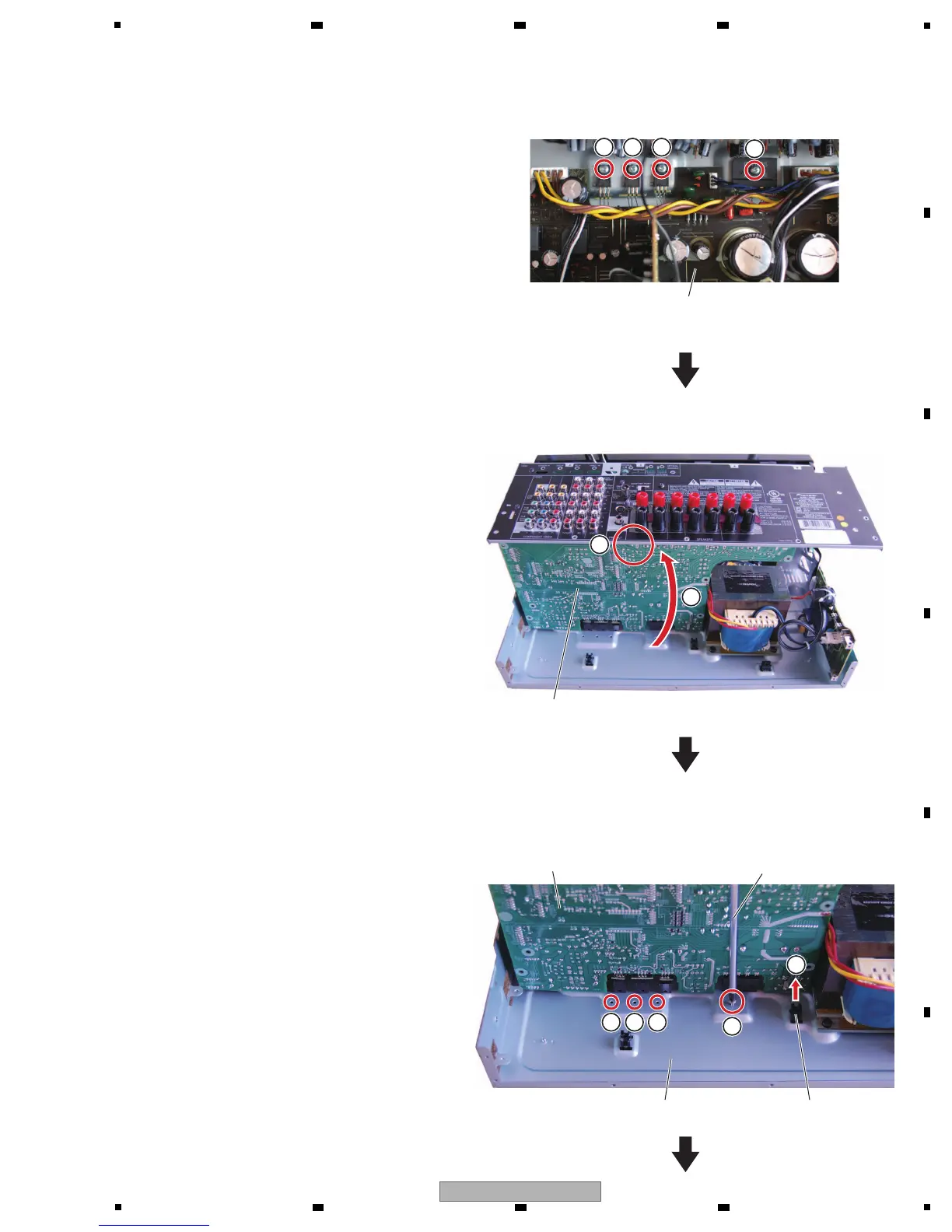
[4-3] Regulator ICs and Recifier diode
(1) Remove the support.
(2) Tighten then loosen the screw in each of the
four holes for temporary joining that are
located on the rear side of the main chassis.
(This is for shaving the thread grooves to
facilitate attachment in the next step.)
Support
MAIN Assy
Main chassis
Screwdriver
1
2
222
 Loading...