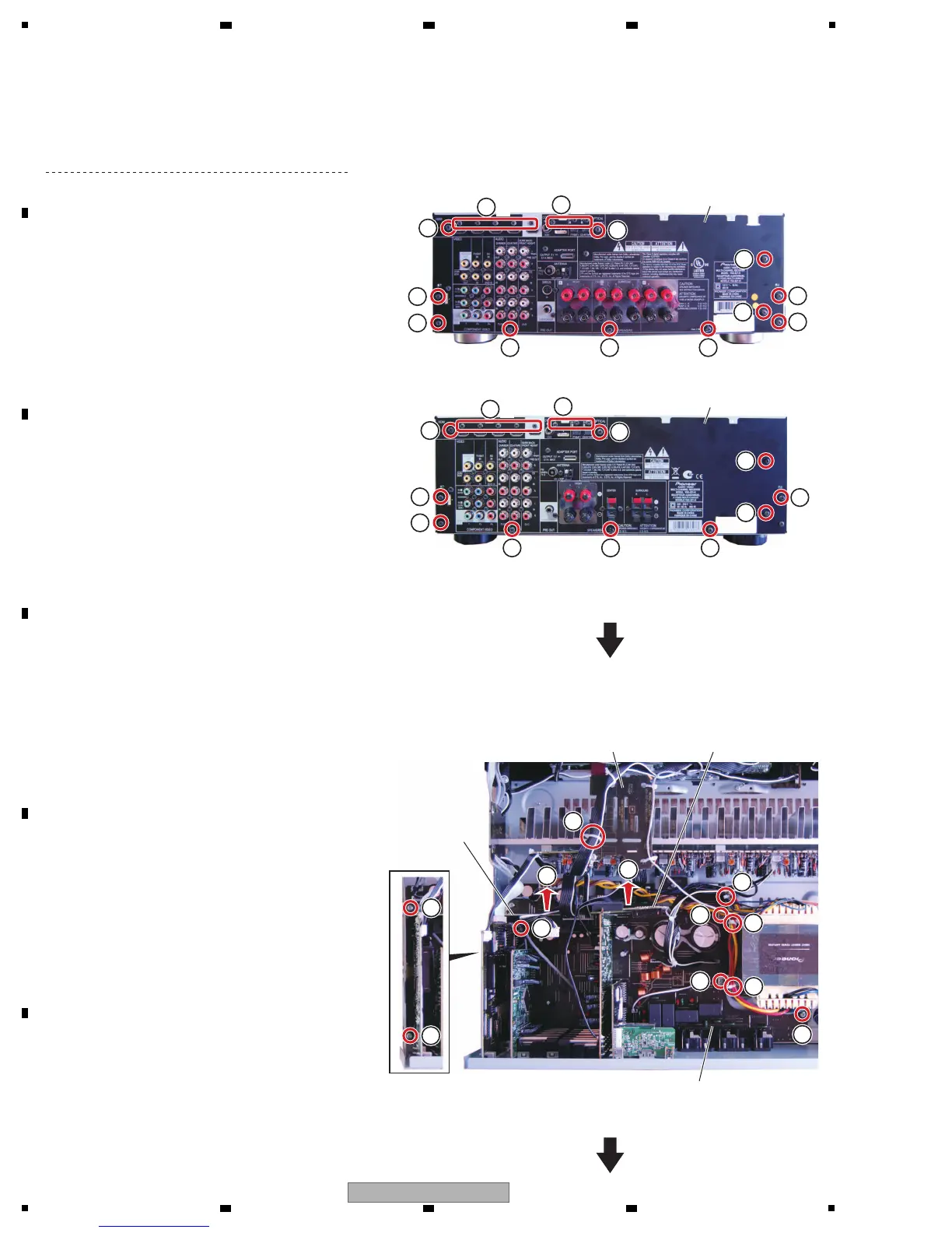
[4] MAIN Assy
[4-1] Chassis back, D-MAIN Assy
Remove the cabinet by removing the 10 screws.
(1) Remove the 14 screws. (BBT30P100FTB)
(2) Remove the five screws. (BSZ30P040FTB)
(3) Remove the D-MAIN Assy.
(See procedure [3].)
1
• Rear view
Chassis back
2
1
1
1
1
1
1
1
1
1
1
1
1 1 1
1 1
×5
1
×3
(VSX-821-K, VSX-921-K)
(VSX-521-K)
1
1
1
• Rear view
Chassis back
2
1
×5
1
×3
[4-2] MAIN Assy
(1) Remove the four screws. (BBZ30P180FTC)
(2) Remove the two screws. (BBZ30P080FTC)
(3) Cut the four binders.
(4) Remove the BRIDGE A and B Assys.
1
1
1
1
3
3
3
3
2
2
WIRE GUIDE A Assy BRIDGE A Assy
MAIN Assy
BRIDGE B
Assy
4
4
 Loading...