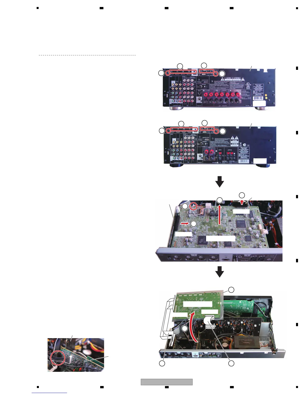
[3] D-MAIN Assy
Remove the cabinet by removing the 10 screws.
(1) Remove the five screws. (BBT30P100FTB)
(2) Remove the five screws. (BSZ30P040FTB)
(3) Cut the binder.
(4) Disconnect the two B to B connectors.
(CP1305, CP1306)
(5) Remove the D-MAIN Assy.
1
• Rear view
Chassis back
2
1
×5
1
×3
(VSX-821-K, VSX-921-K)
(VSX-521-K)
1
• Rear view
Chassis back
2
1
×5
1
×3
D-MAIN Assy
D-MAIN Assy
BRIDGE A Assy
BRIDGE A Assy
AUDIO Assy
CPU Assy
3
4
5
4
CP1306
CP1306
CP1305
CP1305
(6) Connect the two extension jig cables.
(7) Arrange the D-MAIN Assy in the photo below.
(8) Insert any insulation sheet.
Note:
Confirm that a B to B connector of BRIDGE A
Assy is connected to AUDIO Assy tightly.
Insulation sheet
8
6
Borad to board extension
jig cable (GGD1734)
6
Borad to board extension
jig cable (GGD1733)
7
 Loading...