2 - 4 SUSPENSION AND STEERING
GEM Service Manual November 2007
ALIGNMENT
DESCRIPTION
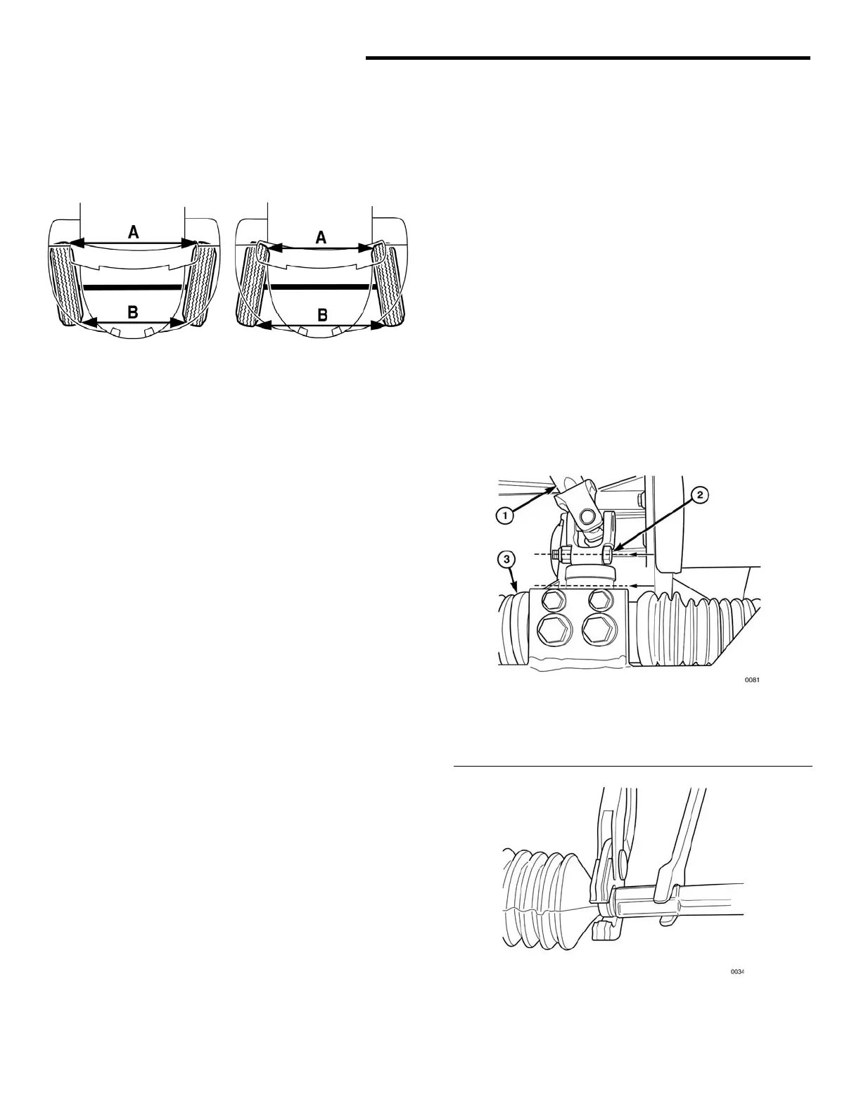
TOP VIEW
Fig. 2 Toe-In vs. Toe-Out
Toe is the only available adjustment in the front
wheel alignment. Toe is the difference between the
leading inside edges and trailing inside edges of
the front tires. It should be measured at a point
above the ground equal to one-half the overall
diameter of the wheel/tire assembly. The
specification is + 1/16 inch toe in.
Wheel toe position out of specification causes
unstable steering, uneven tire wear and steering
wheel off-center.
MEASURING TOE
1. Park the vehicle on a level flat surface.
2. Center the front wheels.
3. Roll car forwards 6-8 ft and apply emergency
brake.
4. Measure distance from the inboard edge of the
tread at the rear of the right front tire to the
inboard edge of the tread at the rear of the left
front tire.
5. Measure distance from the inboard edge of the
tread at the front of the right front tire to the
inboard edge of the tread at the front of the left
front tire.
6. Subtract the front measurement from the rear
measurement. If the front measurement is less
than the rear, the vehicle has toe-in, and is
shown with a plus sign (+1/16"). If the front
measurement is greater than the rear, the
vehicle has toe-out, and the difference is shown
with a minus sign (-1/16").
ADJUSTING TOE
1. Center the front wheels.
2. Inspect the position of the pinch bolt that joins
the steering column shaft to the steering gear.
This bolt must be horizontal and under the shaft
(see Figure 3). If necessary, turn the steering
wheel to put the bolt in this orientation.
Remove and re-center the steering wheel if
required.
3. Lash the steering wheel in the centered
position.
4. Loosen the lock nuts on the tie rods.
5. Use locking pliers to hold the clamp that
secures the small end of the boot to the tie rod.
Take care not to damage the boot.
6. Using a 9/16” wrench, rotate the tie rods so that
the front wheels have the specified toe-in (see
Figure 4).
7. Tighten the lock nuts.
Fig. 3 Pinch Bolt Orientation
1 - Steering shaft
2 - Pinch bolt (parallel to steering gear mounting bracket)
3 - Steering gear
Fig. 4 Tie Rod Adjustment
 Loading...


