CONNECTOR PINOUTS
© Polycom, Inc. 51 VORTEX EF2241 Reference Manual
C
ONNECTOR
P
INOUTS
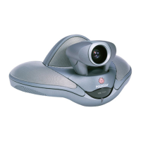
EF Bus
The EF Bus uses RJ45 connectors. These should be
used with category five twisted-pair cable.
The total distance of the EF Bus should be less than
4.5 m.
The EF Bus must be connected so that the EF Bus In
of one box is connected to the EF Bus Out of
another. Connecting the EF Bus In to another EF
Bus In (or Out to Out) will not work.
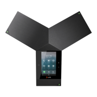
Cat-5 Plug Pinout
1 - White/Orange
2 - Orange
3 - White/Green
4 - Blue
5 - White/Blue
6 - Green
7 - White/Brown
8 - Brown
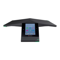
RJ11 Plug Pinout
3 - Ring
4 - Tip
Note: Other pins are not connected. The DAA is not
affected by Tip and Ring wiring reversal.
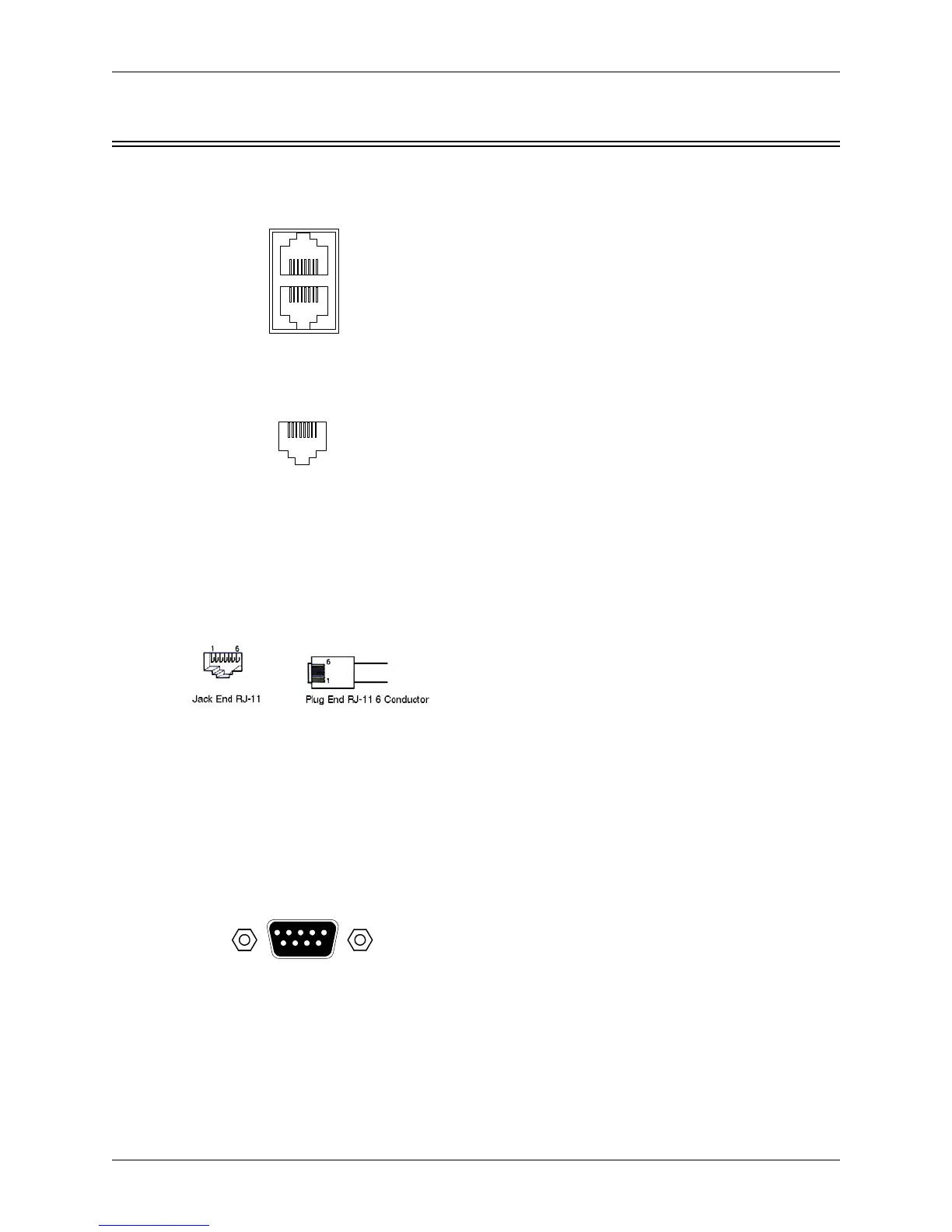
RS-232 Port (9600, 19200, 38400, 8-N-1)
The RS-232 port is wired as DCE. It accepts a male
DB-9 connector. Only pins 2, 3, and 5 are required
by the EF2241 but pins 7 and 8 are supported. Con-
nect pins straight through (do not use null modem).
1 DCD; 2 TXD; 3 RXD 4 DSR; 5 ground; 6 DTR; 7
CTS; 8 RTS; 9 No connection
Baud rate is selectable at 9600, 19200, or 38400.
EF BUS IN
EF BUS OUT
81
81
18
Cat 5 Plug
(Front View)
REMOTE CONTRO
REMOTE CONTRO
RS-232
15
69
 Loading...