INSTRUCTIONS PW220/PW230 15
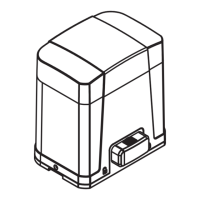
5. Connect the four wires of the light and the antenna to
the PCB terminals and place the wires into the conduit if
necessary.
Figure 2.3.5 (5)
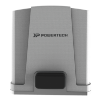
6. Tighten the four screws back on the light base.
Figure 2.3.5 (6)
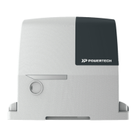
7. Replacing the bulb set. See Figure 2.3.5 (7)
1) Unscrew the flashing light wires from the PCB terminals
and make sure the power of the light is off.
2) Release the three screws (A)、(B)、(C) of the flashing light
cover.
3) Separate the flashing light cover and replace the bulb set
with a new one.
4) Tighten the three screws (A)、(B)、(C) of the flashing light
cover.
Figure 2.3.5 (7)
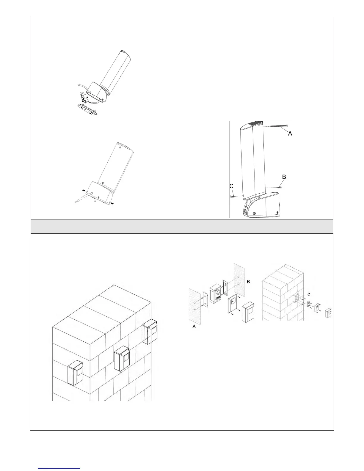
2.3.6 PH-1 Photocells
1. Decide the installation position of the photocells. See
Figure 2.3.6 (1)
Figure 2.3.6 (1)
2. Unscrew the screws and secure the photocells on the post
A, B or C.
Figure 2.3.6 (2) Figure 2.3.6 (3)
3. Wiring connection:
TX: Connect terminals 1(+) and 2(-)on the transmitter with
the terminals 12V and GND on the PC160 PCB.
RX: Connect terminals 1, 2 and 4 on the receiver with the
terminals 12V, GND and SAFE on the PC160 PCB.
And use an extra wire to connect terminals 2 and 5 on the
receiver as a bridge.
See Figure 2.3.6 (4) Figure 2.3.6 (5) and Figure 2.3.8 (4)
 Loading...