INSTRUCTIONS PW220/PW230 19
5. Wiring Connection:
Prepare all the wires of the accessories beforehand and connect the wires to the gear motors and accessories on the PCB as shown
in Figure 2.3.8 (4). All of the wiring connections of the accessories are not requested to distinguish the positive (+) and the
negative (-) polarity.
1) PF-1 Flashing light:
Connect the two wires from the flashing light to the terminal LIGHT and GND on the PCB.
2) PEL-1 Electric Latch:
Connect the two wires from the electric latch to the terminal LATCH and GND on the PCB.
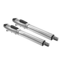
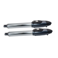
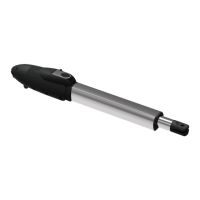
3) PW220/PW230 Gear Motors:
Refer to Figure 2.3.8 (5) and connect the wires separately to the terminals on the PCB.
M1: Connect the motor wire (White +) to the terminals M1 (+), and (Yellow -) to the M1 (-).
M2: Connect the motor wire (White +) to the terminals M2 (+), and (Yellow -) to the M2 (-).
Notes:
For gates opened outward,
M1: Connect the motor wire (Yellow -) to the terminals M1 (+), and (White +) to the terminals M1 (-).
M2: Connect the motor wire (Yellow -) to the terminals M2 (+), and (White +) to the terminals M2 (-).
4) PH-1 Photocells:
Please remove the cover of JP1 and connect the wires to proper terminals.
5) PKS-1 Key Selector:
For Single leaf operation-
Refer to Figure 2.3.8 (4) and connect the two wires from the key selector to the terminal BUTT1
and GND (J7) on the PCB.
For Dual leaf operation-
Refer to Figure 2.3.8 (4) and connect the two wires from the key selector to the terminal BUTT2
and GND (J7) on the PCB.
6) PPB-1 Push Button:
For Single leaf operation-
Refer to Figure 2.3.8 (4) and connect the two wires from the key selector to the terminal BUTT1
and GND (J7) on the PCB.
For Dual leaf operation-
Refer to Figure 2.3.8 (4) and connect the two wires from the key selector to the terminal BUTT2
and GND (J7) on the PCB.
 Loading...