12
PM-1236 v4 1-2017.indd
SPINDLE SPEEDS
The PM-1236 has a nine-speed headstock gearbox with
two shift levers C-B-A and 1-2-3, Figure 3-1. Before
changing speed, STOP THE MOTOR, Figure 3-2, then
move each shift lever to the desired setting. This may
need a little patience because it is not always possible to
go directly from one mesh to another. Move the spindle
back and forth by hand while trying to ease the lever into
its detent (meshed) position. Don’t use the JOG button
in this process — this may cause gear damage.
motor, Figure 3-4. Raise the motor to de-tension the Vee
belts. Move the belts to select the other speed range,
then lower the motor to re-tension. Make certain the mo-
tor is properly aligned, then re-tighten the bolts.
Figure 3-4 Motor bolts
SPINDLE SPEED (RPM)
1 2 3
HIGH
RANGE
A 360 1810 1095
B 100 500 300
C 280 1400 840
LOW
RANGE
A 235 1200 700
B 65 330 200
C 180 910 550
CHUCKS & FACEPLATE
The spindle nose on the PM-1236 accepts D1-4 Cam-
lock chucks, faceplates and other work holding devices.
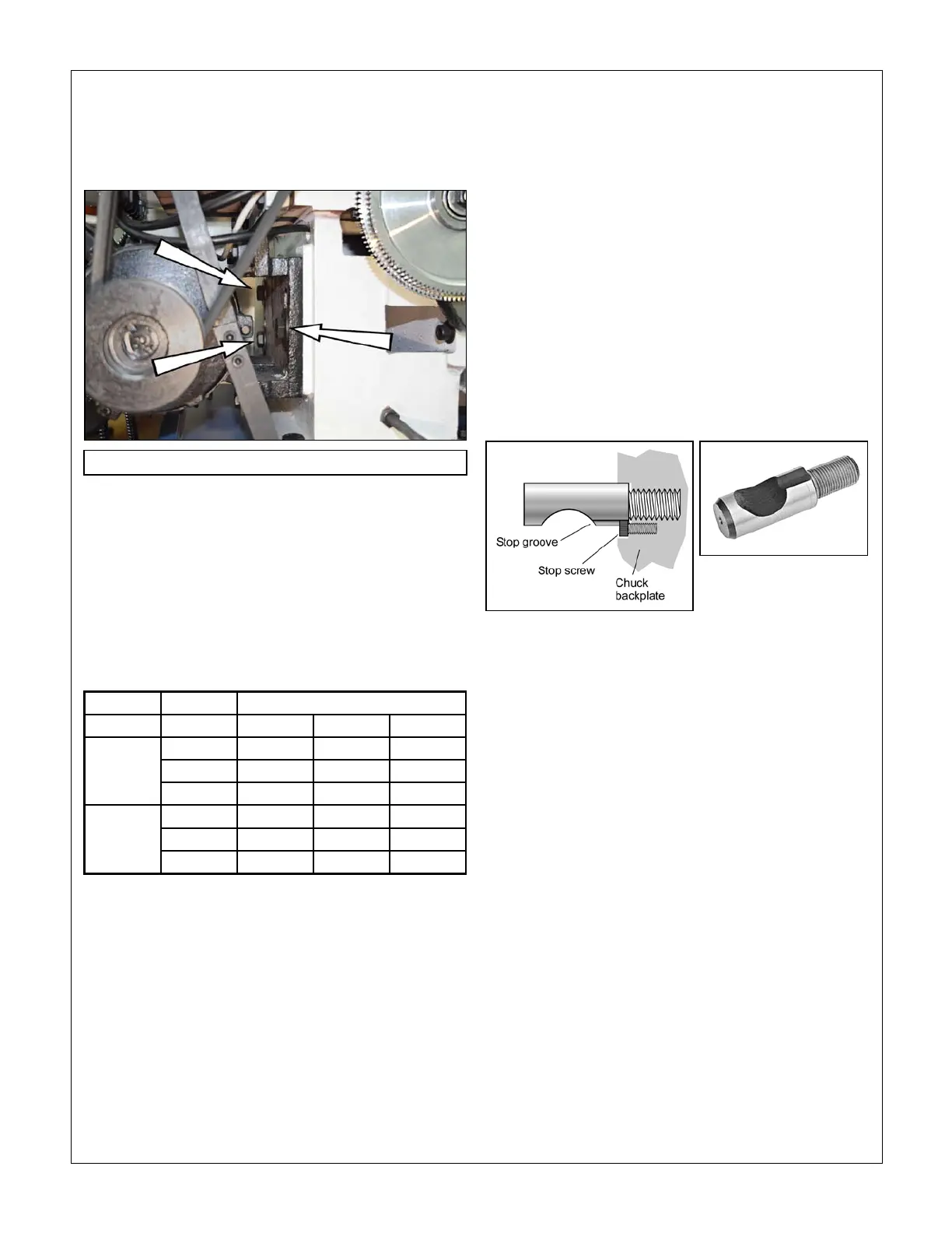
A D1-4 chuck or faceplate is held by three threaded
studs, each with a D-shape crosscut to engage a corre-
sponding cam in the spindle nose, Figure 3-5. The func-
tion of the cams is to pull the chuck backplate inward to
locate its internal taper firmly on the spindle nose.
Alongside each stud is a stop screw, the head of which
fits closely in a groove at the threaded end of the stud.
The function of the stop screw is not to clamp the stud
in place, but instead to prevent it from being unscrewed
when the chuck is not installed.
Figure 3-5 Camlock stud
TO INSTALL A CHUCK
Disconnect the 220V supply from the lathe!
Chucks and faceplates are heavy — the 6 in. and 8 in.
chucks weigh 22 lb and 34 lb. They will cause serious
damage if allowed to fall. Even if a chuck is light enough
to be supported by one hand, the lathe bed should be
protected by a wood scrap, as Figure 3-6. Some users
add packing pieces, even custom-made cradles, to as-
sist “straight line” installation and removal.
Before installing make certain that the mating surfaces
of the chuck/faceplate and spindle are free of grit and
chips.
The cams on the spindle are turned with a square-tip
wrench similar to the chuck key (may be same tool in
some cases).
Recommended procedure:
Select the highest spindle speed (A-2) to allow easier
hand rotation of the spindle. (Alternatively, try moving
the speed selection levers between detents to find
1.
CARRIAGE FEED DIRECTION
The lever below the speed selectors on the front panel,
Figure 3-1, determines whether the power feed is right
to left — the usual direction for turning and thread cutting
— or reversed. The selected direction applies to both the
leadscrew and the carriage/cross slide power feed.
Before changing feed direction, STOP THE MOTOR.
Hand-turn (jiggle) the spindle while feeling for the mesh,
as above

 Loading...
