11PM-727MV v6 2020-10 Copyright © 2020 Quality Machine Tools, LLC
including the heavier knee mills, locking the quill may
oset the spindle by a few thousandths of an inch. If
the edge of the workpiece has been “found” in the quill-
locked condition, this will aect placement of holes
drilled thereafter. Instead, lower the quill with the ne
downfeed control. This is worm driven, so it stays where
it’s put without locking.
NOTE: This does not apply to operations calling for pre-
cise depth control, such as milling. For such operations
the quill is locked to maintain a given depth of cut.
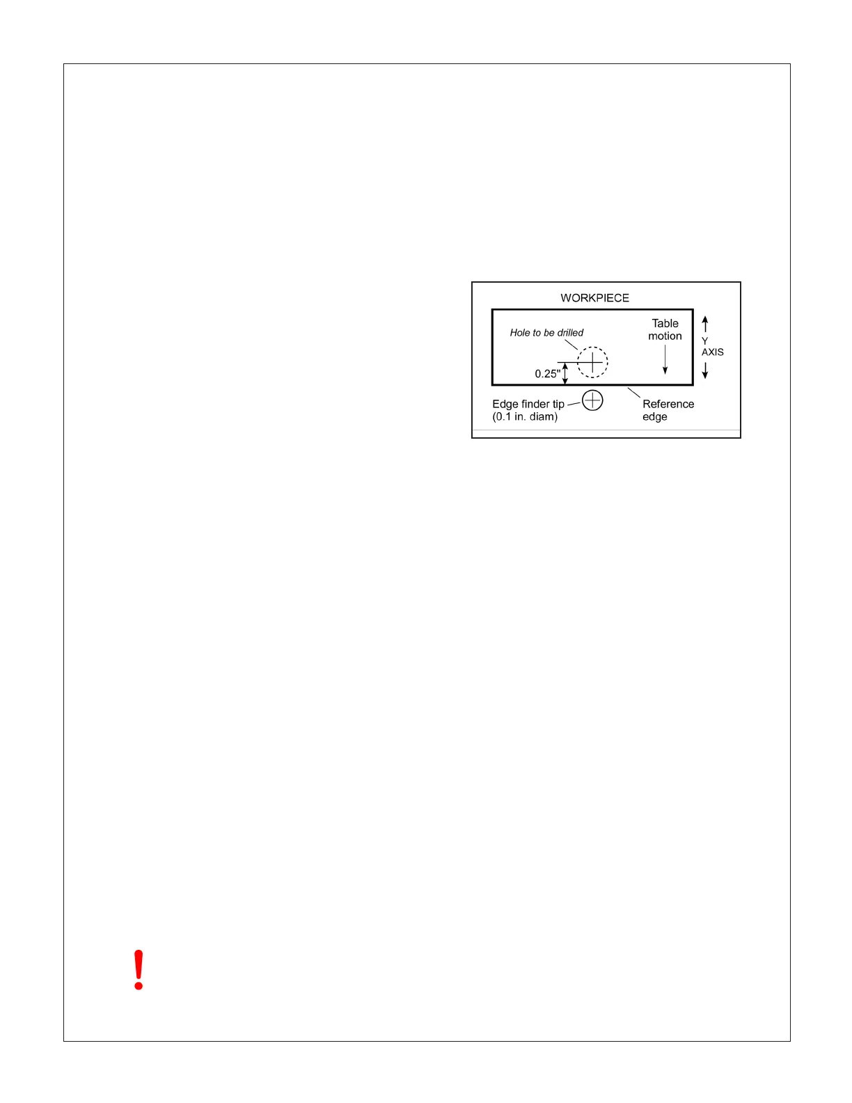
In Figure 3-6 a hole is to be drilled 0.25” on the Y-axis
relative to the front edge of a workpiece in a vise, or
otherwise clamped to the table.
1. Install an edge-nder in collet or chuck (a tip diam-
eter of 0.2” is assumed).
2. Clamp the X-axis by tightening both levers, Figure
3-3.
3. If the reference edge is already to the back the spin-
dle centerline, do nothing; if not, rotate the Y-axis
handwheel clockwise to send the workpiece back-
wards (toward the column).
4. Engage the ne downfeed, Figure 3-5.
5. With the spindle running, lower the quill as neces-
sary using the ne downfeed handwheel; bring the
table forward (counter-clockwise), stopping at the
point where the edge-nder just makes contact (the
tip jumps out of line). Stop the spindle.
6. While holding the Y-axis handwheel to prevent move-
ment, zero the dial.
7. Raise the quill, then rotate the handwheel one exact
full turn counter-clockwise (0.1”) to bring the refer-
ence edge to the spindle centerline.
8. Rotate the handwheel 2-1/2 turns counter-clockwise
to bring 50 on the dial opposite the datum; the spin-
dle is now exactly 0.25” behind the reference edge.
QUILL DOWNFEED
The quill is controlled in two dierent ways, coarse and
ne.
In the drilling mode, coarse feed, the mill functions like a
standard drill press – pull the upper lever toward you to
lower the quill. For milling operations the 3-lever hub is
disengaged, and the quill is controlled by the ne down-
feed handwheel. The quill is locked by a lever on the left
of the headstock, Figure 3-1.
Coarse feed (Figure 3-5)
For drilling operations, loosen knob (4), allowing the le-
ver hub to rotate independently of sleeve (3).
Fine feed (Figure 3-5)
For milling operations calling for precise, repeatable
control of tool depth, tighten knob (4) to engage hub (1)
with the internal taper on sleeve (3). Tighten the Z-axis
clamps, Figure 3-7.
Rotate the ne control knob (2) to raise or lower the quill.
Lower the quill by rotating the ne control knob clock-
wise, positioning it precisely either by counting divisions
on the graduated dial, or by reference to the digital read-
out (DRO), Figure 3-1. Use the locking lever left of the
headstock to hold the quill rmly in position.
If you are counting downfeed divisions be aware of
backlash in the worm drive.
This means that the handwheel must always be turning
in the same direction throughout the entire process,
from setting a reference level to subsequent cutting
passes at specic depths – see the backlash discussion
in “Moving the Table”, above.
Using the DRO – which has no backlash issues – is less
laborious, but remember that the quill is spring-loaded.
This calls for care when releasing the quill locking le-
ver prior to repositioning the quill downward. If the ne
control knob has been allowed to disengage (backed
o counter clockwise), the quill will jump up by 0.01” or
more. To avoid this, make sure the ne control is rmly
clockwise, lightly loading the quill rack, before releasing
the locking lever.
For all spindle positioning op-
erations, with or without DROs,
avoid using the quill lock.
Figure 3-6 Spindle positioning example
Why not use the lock? On vertical mills of this type,
X & Y-AXIS POSITIONING BY COUNTING
DIVISIONS
 Loading...

