9PM-727MV v6 2020-10 Copyright © 2020 Quality Machine Tools, LLC
Section 3 USING THE MILL
Allow the spindle to stop com-
pletely before shifting gears
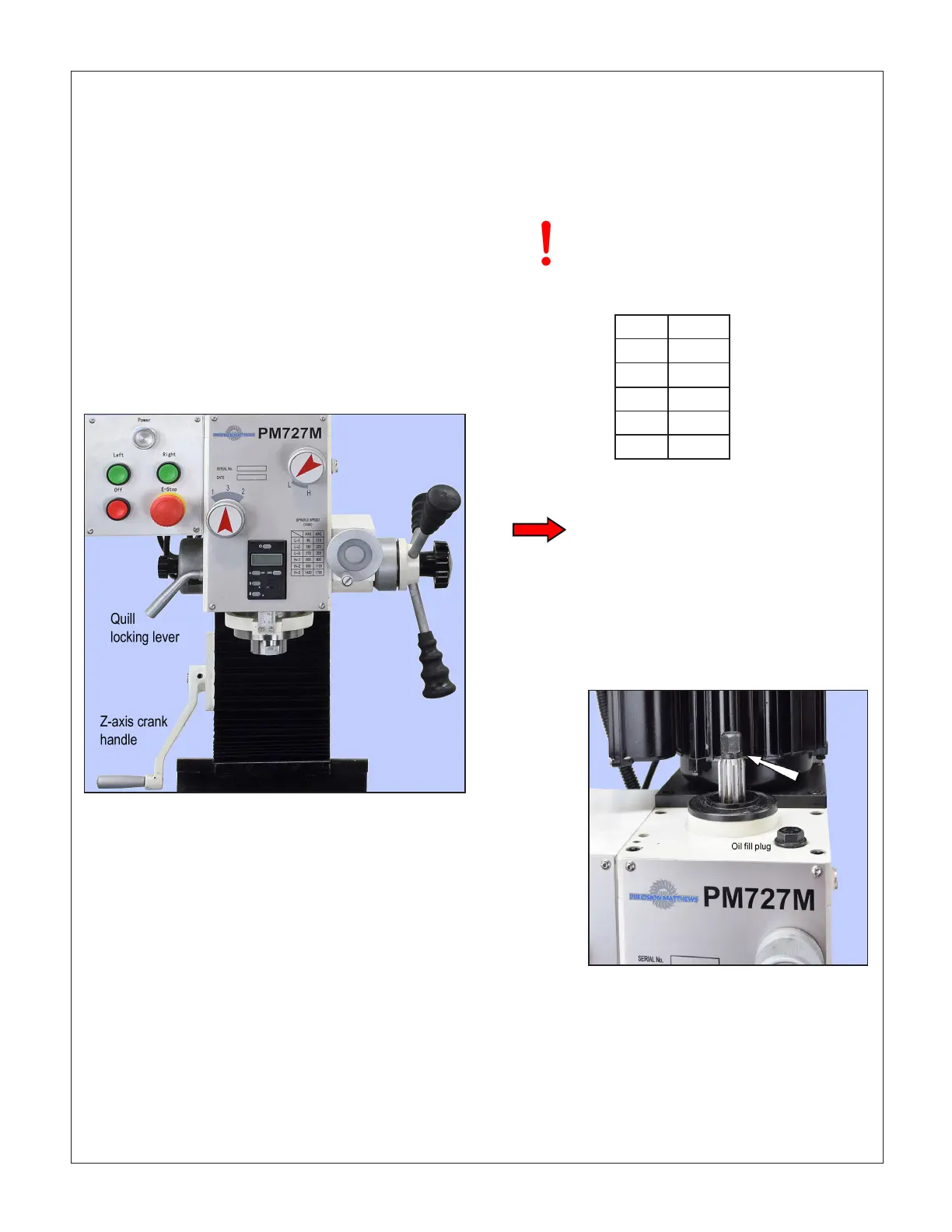
L-1 115
L-2 220
L-3 320
H-1 600
H-2 1120
H-3 1700
FRONT PANEL CONTROLS
Connect the mill to a 110Vac outlet. Press the Power
lamp switch, top center Figure 3-1, to energize the
control circuit (the lamp should light). This is a latching
switch – press once to energize, press again to de-en-
ergize.
The E-stop button, bottom right, is in series with the
Power switch. Like the Power switch, it de-energizes
the control circuit completely, but it should be used only
for its intended purpose – emergency disconnect. Once
the E-stop button is pushed in, it stays in until twisted
clockwise to release.
The spindle drive motor is controlled by the three push
buttons:
Left = Forward (cw, looking down, used for
most milling/drilling operations)
Right = Reverse (ccw, looking down)
O = Stop
SPINDLE SPEEDS
This is a gear-head machine with a constant speed mo-
tor and a two-stage gearbox providing a choice of six
spindle speeds. The rst stage (L-H) selects the speed
range, high or low; the second stage (1-3-2) selects a
specic speed within that range.
Before switching on the spindle motor be sure that
Excessive cutter noise, chatter, poor
nish and tool wear are often the result
of too high a feed rate, and/or too high a
spindle speed. If unsure, go slow!
Spindle speeds (rpm)
INSTALLING & REMOVING TOOLING
The spindle and drawbar are designed for R-8 taper
collets, drill chucks and other arbors with the standard
7/16”-20 internal thread.
When installing or removing R8 tooling, set the spindle
speed to L1 for the best braking action. Alternatively, an
adjustable wrench can be used to grip the ats on the
bottom end of the spindle.
To install: Hand-thread the drawbar into the R-8 device
until the washer, arrowed in Figure 3-2, is seated on the
Figure 3-1 Motor controls, gear shifters & DRO
both stages are properly engaged. Hand-rotate (jiggle)
the spindle forward and back while applying light pres-
sure on each gear-shift knob, listening for the click as
the gears engage.
Figure 3-2 Spindle & drawbar (arrowed)
 Loading...

