17PM-727MV v6 2020-10 Copyright © 2020 Quality Machine Tools, LLC
Figure 4-2 Quill rack
QUILL RACK & PINION
Lower and lock the quill, Figure 4-2. Using a sti ux
brush, clean the visible portions of the rack and pinion.
Raise and lower the quill to expose the remainder of the
working surfaces, locking and cleaning at each setting.
SPINDLE BEARINGS
The spindle runs on grease-lubricated tapered roller
bearings. These should be serviced every 500 hours
of running time. Thoroughly clean each bearing assem-
bly then repack with a grease such as Kluber Isoex
(auto shop wheel bearing grease can be substituted in
low-load, low rpm operations). Do not over-pack the
bearings! Bearing manufacturers recommend that the
free volume between inner and outer should be no more
than 30% lled with grease. (If smothered with grease,
bearings are subject to overheating.)
BOTH screw heads must be tight against the
gib ends. If you loosen one, tighten the other.
Remove the way covers for access to the back
of the Y gib and bottom of the Z gib.
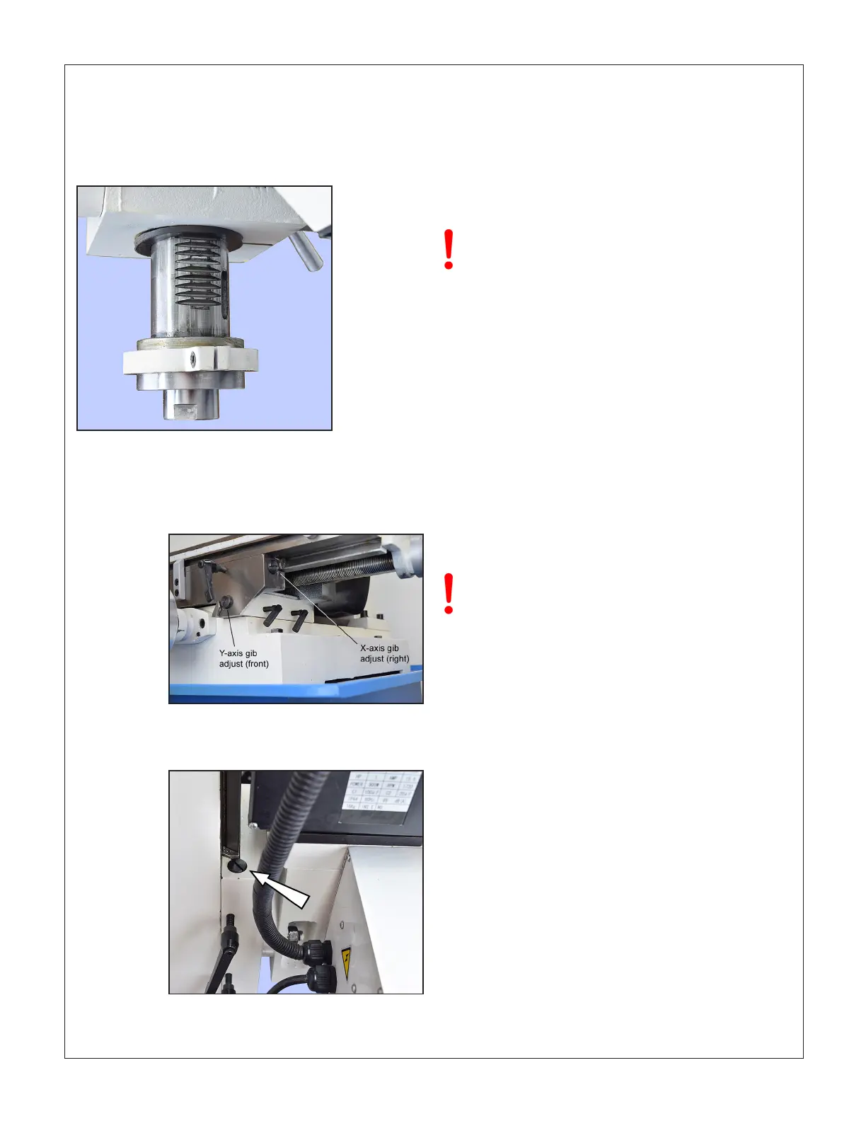
GIB ADJUSTMENT
Gibs on the X, Y and Z axes control the t of the mating
dovetailed surfaces. They are gently-tapered lengths of
Figure 4-3 X and Y-axis gib adjustment
The back adjustment screw for the Y axis gib
is under the solid way cover
Figure 4-4 Z-axis gib adjustment (top)
The lower adjustment screw is under the
pleated way cover
LEADSCREW BACKLASH CORRECTION
When alternating between clockwise and counter clock-
wise rotation of the X or Y leadscrews, the handwheel
moves freely a few degrees but the table stays put. This
is backlash, a feature of all leadscrews other than the
precision variety found on CNC machines. The accept-
able amount of lost motion depends on the user, but
0.005” is generally a good compromise. Smaller num-
bers are possible, but overdoing it can lead to premature
wear of leadscrew and nut.
Excessive backlash can be corrected by compressing
the leadscrew nut. For the X-axis this is done by tighten-
ing the socket head screw in Figure 4-5. A long-handled
4 mm hex wrench is required, ideally one with an ex-
tra-thick shank to minimize exing. The corresponding
adjustment for the Y-axis, Figure 4-6, is concealed by
the solid way cover. It is more dicult to get to because
access to the screw is partly blocked by the leadscrew
itself.
ground cast iron located by opposing screws at each
end. Adjusting them is a trial and error process that
takes time and patience. Aim for the best compromise
of rigidity and reasonably free table movement. Too tight
means accelerated wear on the ways and leadscrews.
Too free means workpiece instability, inaccuracies and
chatter.
Especially during the rst 10 hours of running time
check that the spindle runs smoothly, without ex-
cessive heat build up (the spindle will run warm
when used at high speeds over long periods, but
should not be uncomfortably hot). Overheating can
be due to excessive grease, see above, or an over-
tight spanner nut at the upper end of the spindle.
Call Precision Matthews for guidance.
 Loading...

