 Loading...
Do you have a question about the protech PA-6225 and is the answer not in the manual?
| Display Size | 5.5 inch |
|---|---|
| Touch Technology | Capacitive multi-touch |
| Processor | Quad-Core 1.3GHz |
| RAM | 2GB |
| Operating System | Android 8.1 |
| Resolution | 720 x 1280 |
| Internal Storage | 16GB |
| Connectivity | 4G |
Provides an overview of the PA-6225 Series User Manual and its contents.
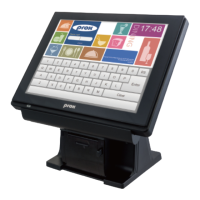
Illustrates the physical layout and key components of the PA-6225 POS system.
Details the hardware specifications of the PA-6225 system including CPU, memory, and OS support.
Outlines essential safety guidelines for operating and handling the PA-6225 system.
Details the rear I/O ports and their pin assignments for the system's connectivity.
Describes the system's power button, various ports, connectors, and jumper settings.
Shows the PB-6822 mainboard layout, component positions, and jumper configurations.
Explains the procedure for setting jumpers and interpreting their diagrams for hardware configuration.
Details component locations and pin assignments for different printer boards (PDAC-3100, MB-1030, MB-1011/1013).
Shows component locations and pin assignments for the VFD board (MB-4103, LD720).
Details component locations and pin assignments for various MSR boards (ID-TECH, SYSKING, MB-3012).
Covers the installation of system drivers including chipset, VGA, LAN, Sound, and Touchscreen.
Lists commands and driver guides for peripheral devices like printer, VFD, and MSR.
Explains API package contents, procedures, and sample code for application development.
Details accessing and operating the BIOS setup utility, including main, advanced, security, boot, and save/exit.
Provides exploded diagrams for panel PC components like cable cover, storage, and touchscreen.
Shows exploded diagrams for different stand types, including small and multi-functional stands.
Illustrates exploded diagrams for peripheral devices like MSR, i-Button, Fingerprint, VFD, and 2nd Display.
Details the exploded diagram for packing components, including PPC and POS packing.