QS3.241
Q-Series
24V, 3.4A, SINGLE PHASE INPUT
Jul. 2020 / Rev. 2.3 DS-QS3.241-EN
All parameters are specified at 24V, 3.4A, 230Vac, 25°C ambient and after a 5 minutes run-in time unless otherwise noted.
www.pulspower.com Phone +49 89 9278 0 Germany
23/26
22.5. CHARGING OF BATTERIES
The power supply can be used to charge lead-acid or maintenance free batteries. (Two 12V batteries in series)
Instructions for charging batteries:
a) Set output voltage (measured at no load and at the battery end of the cable) very precisely to the end-of-charge
voltage.
End-of-charge voltage 27.8V 27.5V 27.15V 26.8V
Battery temperature 10°C 20°C 30°C 40°C
b) Use a 15A or 16A circuit breaker (or blocking diode) between the power supply and the battery.
c) Ensure that the output current of the power supply is below the allowed charging current of the battery.
d) Use only matched batteries when putting 12V types in series.
e) The return current to the power supply (battery discharge current) is typ. 6.3mA when the power supply is
switched off (except in case a blocking diode is utilized).
22.6. PARALLEL USE TO INCREASE OUTPUT POWER
Power supplies from the same series (Q-Series) can be paralleled to increase
the output power. The output voltage shall be adjusted to the same value
(±100mV) with the same load conditions on all units, or the units can be left
with the factory settings.
If more than three units are connected in parallel, a fuse or circuit breaker
with a rating of 4A or 6A is required on each output. Alternatively, a diode or
redundancy module can also be utilized.
Keep an installation clearance of 15mm (left / right) between two power
supplies and avoid installing the power supplies on top of each other. Do not
use power supplies in parallel in mounting orientations other than the standard mounting orientation (input terminals
on bottom and output terminals on the top of the unit) or in any other condition where a derating of the output
current is required (e.g. altitude, above 60°C, …).
Pay attention that leakage current, EMI, inrush current, harmonics will increase when using multiple power supplies.
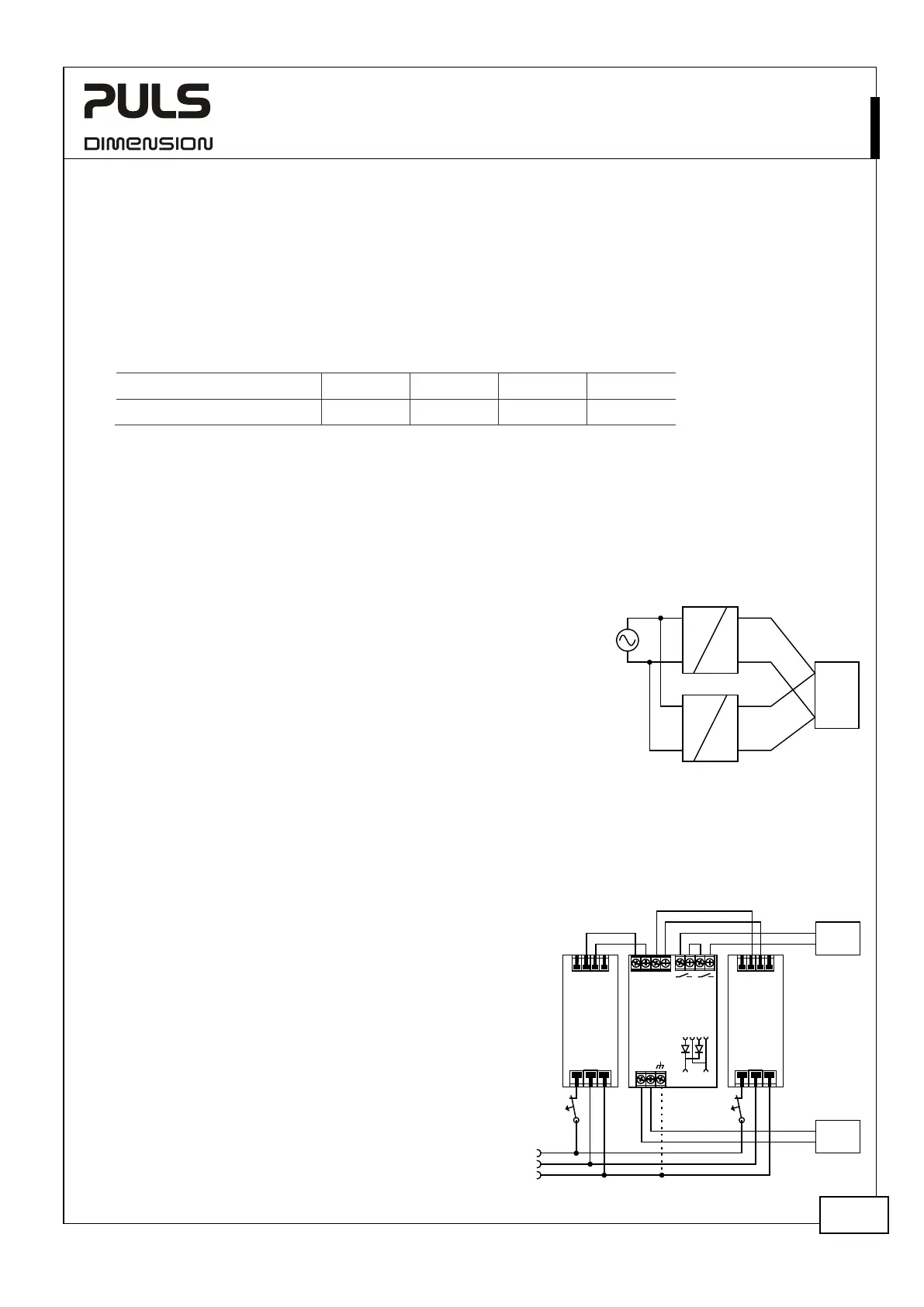
22.7. PARALLEL USE FOR REDUNDANCY
Power supplies can be paralleled for redundancy to gain higher
system availability. Redundant systems require a certain amount
of extra power to support the load in case one power supply
unit fails. The simplest way is to put two power supplies in
parallel. This is called a 1+1 redundancy. In case one power
supply unit fails, the other one is automatically able to support
the load current without any interruption. Redundant systems
for a higher power demand are usually built in a N+1 method.
E.g. five power supplies, each rated for 3.4A are paralleled to
build a 13.6A redundant system. For N+1 redundancy the same
restrictions apply as for increasing the output power, see also
section 23.6.
Please note: This simple way to build a redundant system does
not cover failures such as an internal short circuit in the
secondary side of the power supply. In such a case, the defective
Unit A
AC
DC
Unit B
AC
DC
-
+
-
+
Load
+
-
Failure
Monitor
24V,3.4A
Load
optional
I I
L
N
PE
YRM2.DIODE
Redundancy Module
+
-
Output
+
-
I
N
1
+
-
I
N
2
I
N
1 I
N
2
L N PE
+ +
- -
QS3.241
Power
Supply
24V,3.4A
L N PE
+ +
- -
QS3.241
Power
Supply
24V,3.4A
 Loading...