QS3.241
Q-Series
24V, 3.4A, SINGLE PHASE INPUT
Jul. 2020 / Rev. 2.3 DS-QS3.241-EN
All parameters are specified at 24V, 3.4A, 230Vac, 25°C ambient and after a 5 minutes run-in time unless otherwise noted.
www.pulspower.com Phone +49 89 9278 0 Germany
24/26
unit becomes a load for the other power supplies and the output voltage can not be maintained any more. This can be
avoided by utilizing decoupling diodes which are included in the redundancy module YRM2.DIODE.
Recommendations for building redundant power systems:
a) Use separate input fuses for each power supply.
b) Monitor the individual power supply units. Therefore, use the Input-OK relay contact of the YRM2.DIODE
redundancy module.
c) It is desirable to set the output voltages of all units to the same value (± 100mV) or leave it at the factory setting.
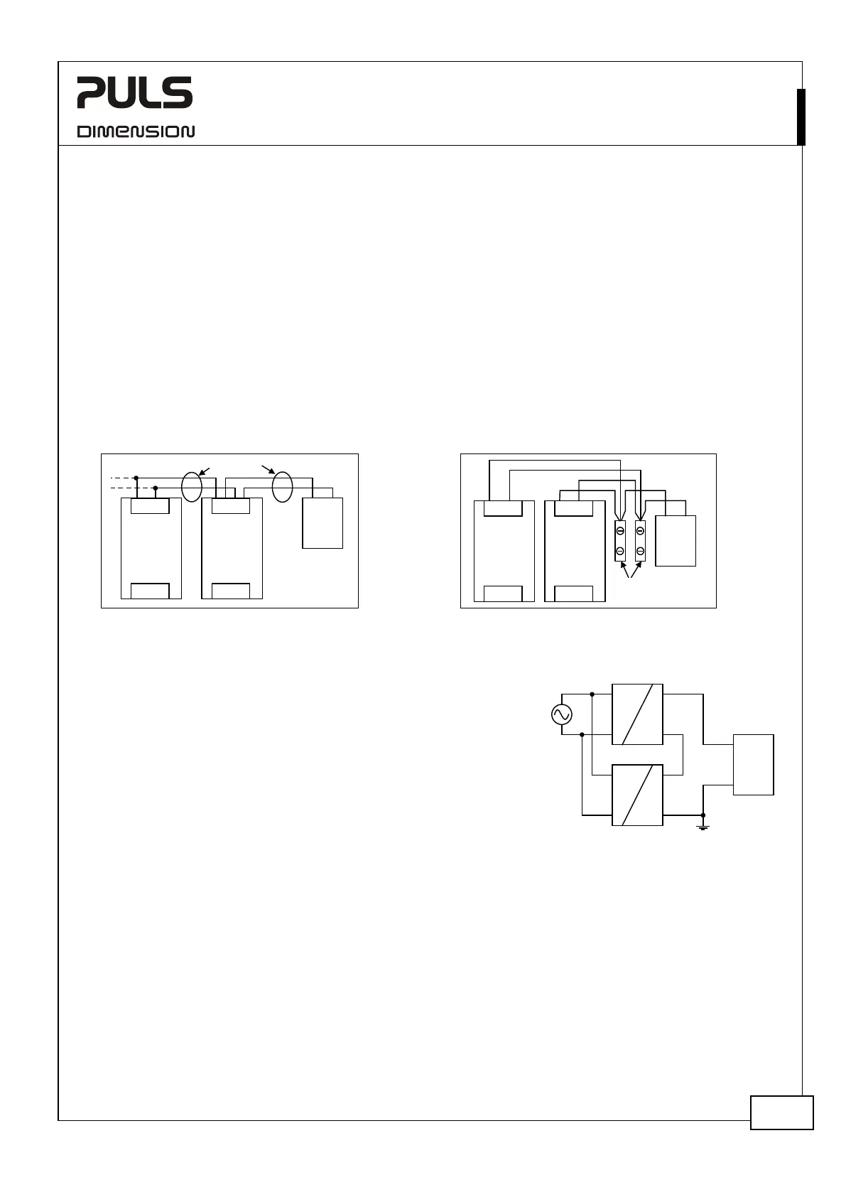
22.8. DAISY CHAINING OF OUTPUTS
Daisy chaining (jumping from one power supply output to the next) is allowed as long as the average output current
through one terminal pin does not exceed 13A. If the current is higher, use a separate distribution terminal block as
shown in Fig. 23-6.
Fig. 23-5 Daisy chaining of outputs Fig. 23-6 Using distribution terminals
Power
Supply
+
+
- -
Input
Output
Load
+
-
max 13A!
Power
Supply
+ +
- -
Input
Output
Load
+
-
Distribution
Terminals
Power
Supply
+ +
- -
Input
Output
Power
Supply
+ +
- -
Input
Output
22.9. SERIES OPERATION
Power supplies of the same type can be connected in series for higher
output voltages. It is possible to connect as many units in series as needed,
providing the sum of the output voltage does not exceed 150Vdc. Voltages
with a potential above 60Vdc are not SELV any more and can be dangerous.
Such voltages must be installed with a protection against touching.
Earthing of the output is required when the sum of the output voltage is
above 60Vdc.
Avoid return voltage (e.g. from a decelerating motor or battery) which is
applied to the output terminals.
Keep an installation clearance of 15mm (left / right) between two power supplies and avoid installing the power
supplies on top of each other. Do not use power supplies in series in mounting orientations other than the standard
mounting orientation (input terminals on bottom and output terminals on the top of the unit).
Pay attention that leakage current, EMI, inrush current, harmonics will increase when using multiple power supplies.
22.10. INDUCTIVE AND CAPACITIVE LOADS
The unit is designed to supply any kind of loads, including unlimited capacitive and inductive loads.
Unit A
AC
DC
Unit B
AC
DC
-
+
-
+
Load
+
-
Earth
(see notes)
 Loading...