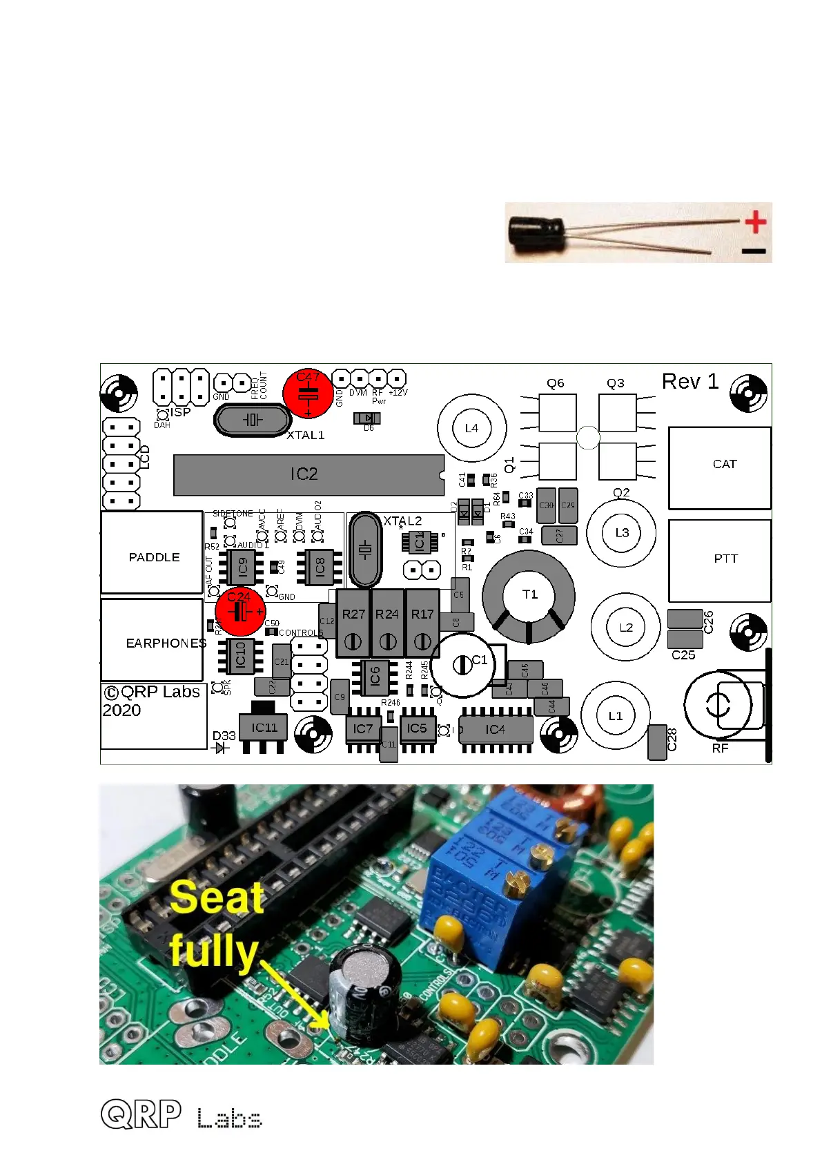
3.17 Install 470uF capacitors
There are two 470uF capacitors in the kit: C24, C47. These are polarized electrolytic
capacitors and MUST be installed with the correct orientation! The capacitor NEGATIVE
wire must be installed in the hole indicated on the PCB silkscreen and the layout diagram
by the solid black bar; the POSITIVE wire must be installed in the hole indicated on the
PCB silkscreen and the layout diagram by the hollow bar and the + symbol.
Electrolytic capacitors are also supplied with one wire
longer than the other. The + wire is the longer wire,
the – wire is the shorter one (see photo, right).
These capacitors must be installed on the PCB so
that they are sitting flush with the PCB, with no gap between the PCB and the bottom of the
capacitor.
44

 Loading...