Smart Module Series
SC200E_Series_Hardware_Design 11 / 115
Figure 42: Recommended Footprint (Top View) ...................................................................................... 102
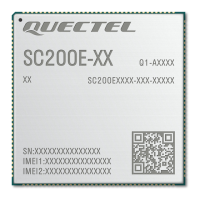
Figure 43: Top and Bottom Views of the Module ..................................................................................... 103
Figure 44: Recommended Reflow Soldering Thermal Profile ................................................................. 105
Figure 45: Carrier Tape Dimension Drawing ............................................................................................ 107
Figure 46: Plastic Reel Dimension Drawing ............................................................................................ 107
Figure 47: Packaging Process ................................................................................................................. 108

 Loading...