EasyManuals Logo
Home>Quectel>GSM/GPRS Modules>SC200E Series

Quectel SC200E Series User Manual

Quectel SC200E Series
116 pages
To Next Page IconTo Next Page
To Previous Page IconTo Previous Page
Page #55 background imageLoading...
Page #55 background image
Smart Module Series
SC200E_Series_Hardware_Design 54 / 115
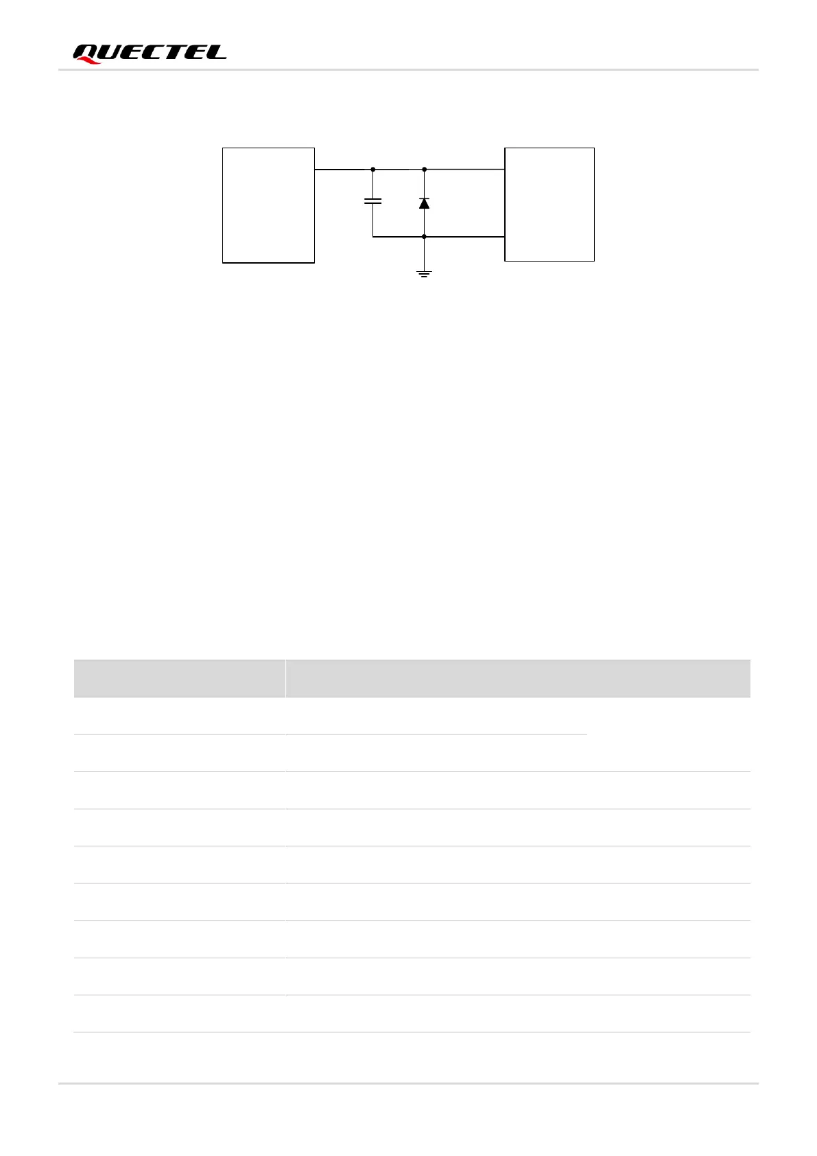
The motor is driven by an exclusive circuit, and a reference circuit is shown below.
Module
VIB+
Motor
VIB-
C1
VIB_DRV_P
D1
33 pF
Figure 18: Reference Circuit for Motor Connection
When the motor stops working and the VIB_DRV_P is disconnected, the redundant electricity on the
motor can be discharged from the circuit loop formed by diodes, thus avoiding damage to components.
3.17. LCM Interface
The module provides one LCM interface, which is MIPI DSI standard compliant. The interface supports
high-speed differential data transmission and supports HD+ display (1680 × 720 @ 60 fps). The pin
definition of the LCM interface is shown below.
Table 20: Pin Definition of LCM Interface
Pin Name
Pin No.
I/O
Description
Comment
LCD_RST
49
DO
LCD reset
1.8 V power domain.
LCD_TE
50
DI
LCD tearing effect
DSI_CLK_N
52
AO
LCD MIPI clock (-)
-
DSI_CLK_P
53
AO
LCD MIPI clock (+)
-
DSI_LN0_N
54
AO
LCD MIPI lane 0 data (-)
-
DSI_LN0_P
55
AO
LCD MIPI lane 0 data (+)
-
DSI_LN1_N
56
AO
LCD MIPI lane 1 data (-)
-
DSI_LN1_P
57
AO
LCD MIPI lane 1 data (+)
-
DSI_LN2_N
58
AO
LCD MIPI lane 2 data (-)
-

Table of Contents

Questions and Answers:

Question and Answer IconNeed help?

Do you have a question about the Quectel SC200E Series and is the answer not in the manual?

Quectel SC200E Series Specifications

General IconGeneral
BrandQuectel
ModelSC200E Series
CategoryGSM/GPRS Modules
LanguageEnglish

Related product manuals