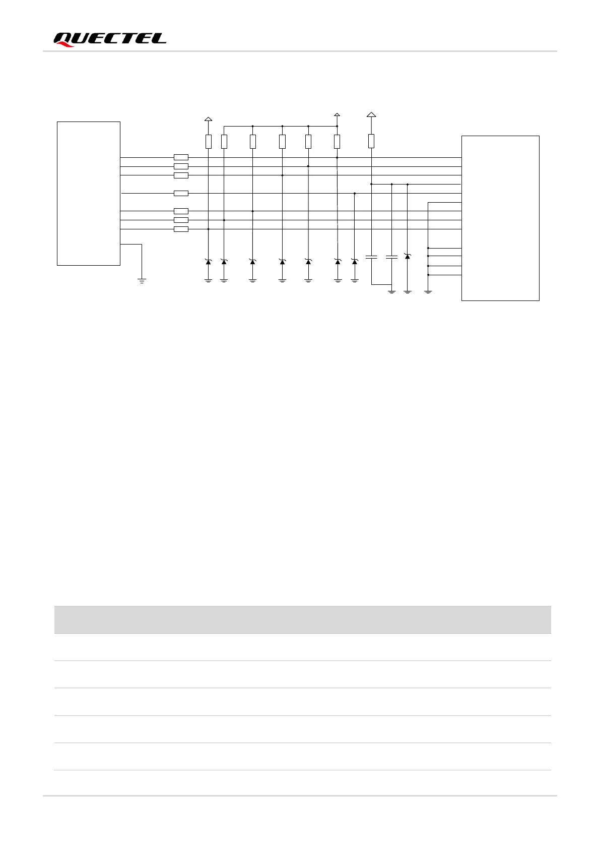
Figure 17: Reference Circuit for the SD Card Interface
SD_LDO21 is the power supply for the SD card and can provide up to 841 mA output current. Due to the
high output current, it is recommended that the trace width should be at least 0.8 mm. To ensure output
current stability, add a 4.7 μF and a 33 pF capacitor in parallel near the SD card connector.
SD_CMD, SD_CLK, SD_DATA0, SD_DATA1, SD_DATA2, and SD_DATA3 are all high-speed signal lines.
In PCB design, control the characteristic impedance of them to 50 Ω, and do not cross them with other
traces. It is recommended to route the traces on the inner layer of the PCB and keep them of the same
length. Additionally, SD_CLK needs ground shielding separately.
Trace length requirements:
⚫ Control the impedance to 50 Ω ±10 % and add ground shielding.
⚫ Keep the trace length difference among SD_CLK, SD_CMD and SD_DATA less than 2 mm.
Table 15: SD Card Trace Length Inside the Module

 Loading...