Fluid Scavenging System
Fluid from the separator element is returned to the inlet
valve byway of a scavenger tube positioned on the
outside of the fluid separator element, through an
orifice contained in a fitting mounted on the side of the
air/fluid reservoir. A nylon scavenge tube then carries
the oil to the compressor.
Cleaning of the orifice should be performed, whichever
comes first of the following conditions:
● When no fluid is seen moving through the nylon
scavenging tube.
● When excessive fluid carryover is detected.
● Every separator change.
“Twice per year.
NOTE: Do not ream the orifice or change the orifice
size.
Control Line Air Filter
Condensate collection in the bowl must be drained.
The control line filtration uses the float method of
automatic drain. Function of this automatic drain
should be observed daily for operation and immediate
repairs made if the filter should corrode.
Compressor Shaft Fluid Seal
Compressor shaft seals are wear items that may
eventually have to be replaced. A complete
understanding of the installation procedure and special
tools are required for a successful seal replacement. The
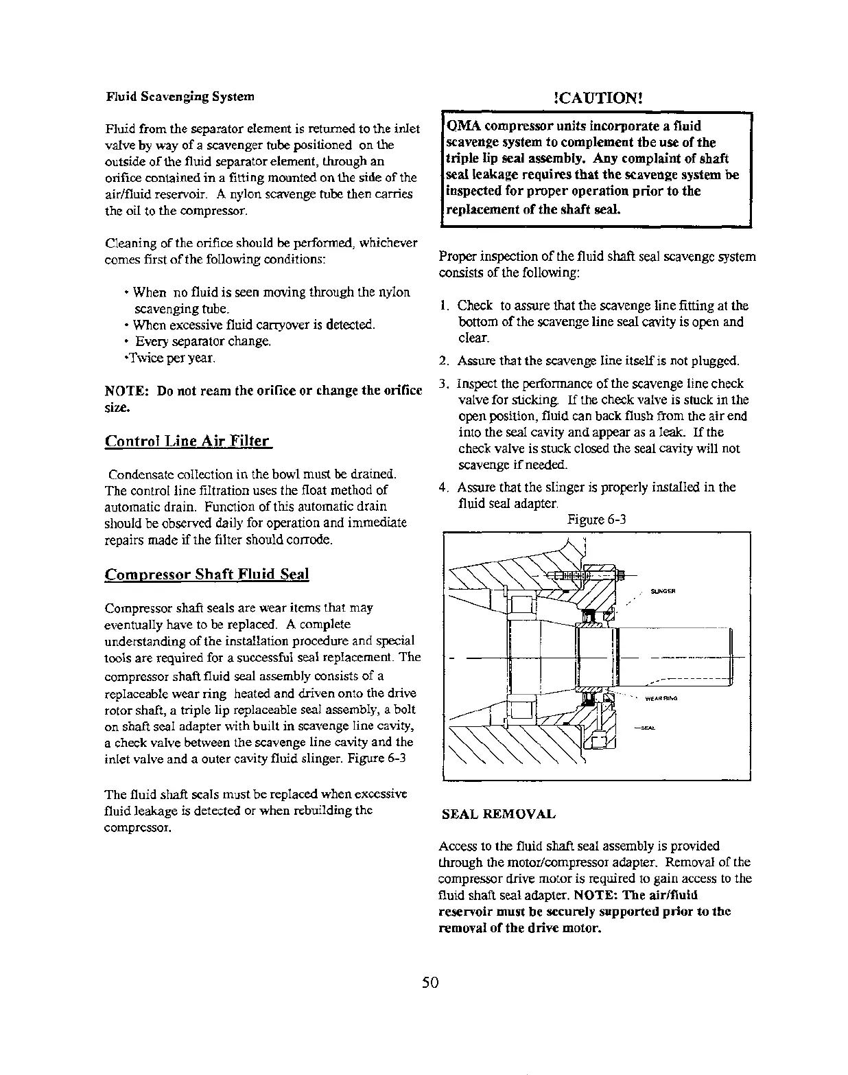
compressor shaft fluid seal assembly consists of a
replaceable wear ring heated and driven onto the drive
rotor shaft, a triple lip replaceable seal assembly, a bolt
on shaft seal adapter with built in scavenge line cavity,
a check valve between the scavenge line cavity and the
inlet valve and a outer cavity fluid slinger. Figure 6-3
The fluid shaft seals must be replaced when excessive
fluid leakage is detected or when rebuilding the
compressor.
!CAUTION!
QMA compressor units incorporate a fluid
scavenge system to complement the use of the
triple lip seal assembIy. Any complaint of shaft
.waIleakage requires that the scavenge system be
inspected for proper operation prior to the
replacement of the shaft seal.
Proper inspection of the fluid shaft seal scavenge system
consists of the following:
1.
2.
3.
4.
Check to assure that the scavenge line fitting at the
bottom of the scavenge line seal cavity is open and
clear.
Assure that the scavenge line itself is not plugged.
Inspect the performance of the scavenge line check
valve for sticking. If the check valve is stuck in the
open position, fluid can back flush from the air end
into tie seal cavity and appear as a leak. If the
check valve is stuck closed the seal cavity will not
scavenge if needed.
Assure that the slinger is properly installed in the
fluid seal adapter. - - -
Figure 6-3
SEAL REMOVAL
Access to the fluid shaft seal assembly is provided
through the motor/compressor adapter. Removal of the
compressor drive motor is required to gain access to the
fluid shaft seal adapter. NOTE: The air/fluid
reservoir must be securely supported prior to the
removal of the drive motor.
50
 Loading...