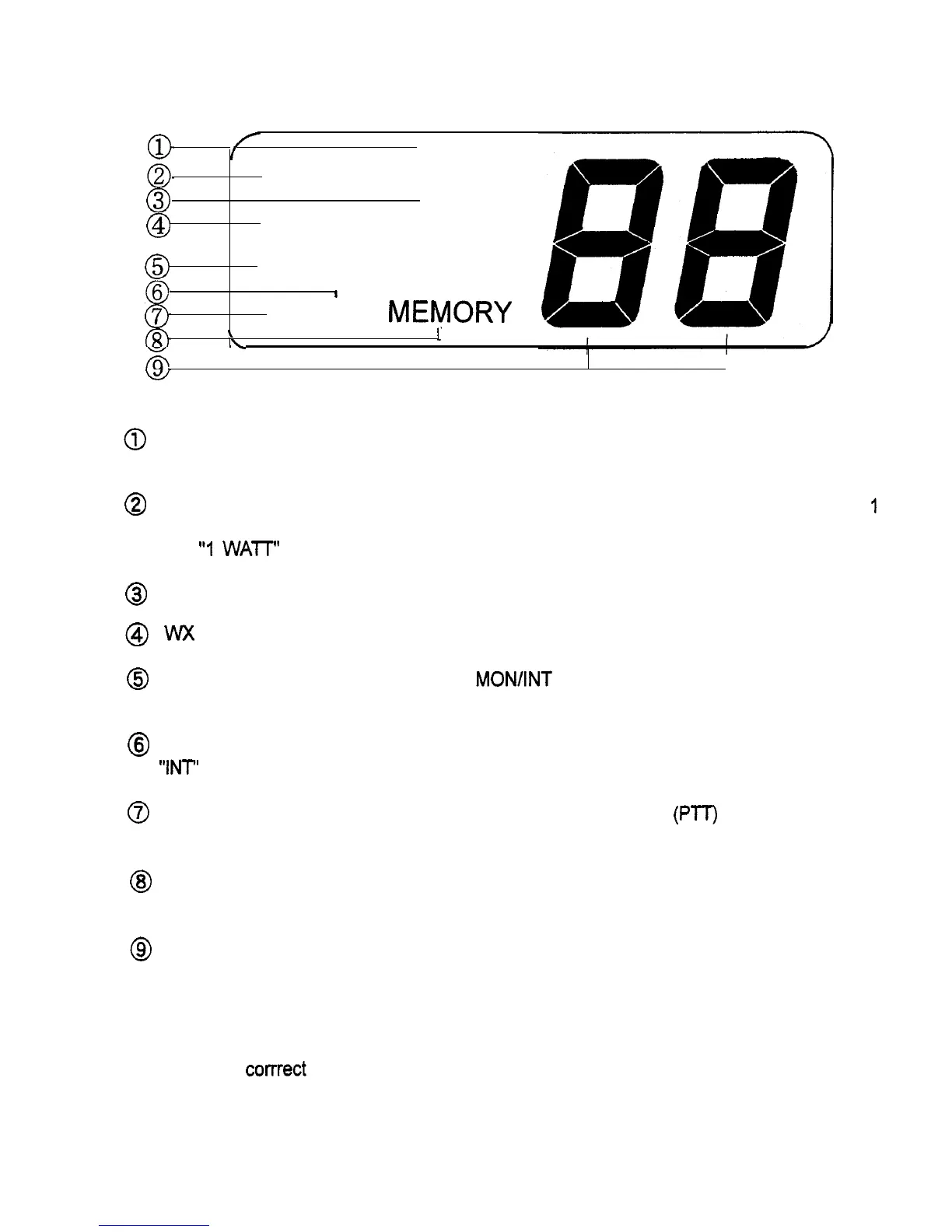
3.2.2 LCD Display
A number of characters appear on the LCD display in different locations. The following list
describes the characters as well as when and where they will appear.
/
I
I
1 WATT SCAN
0
I
@
wx ALERT
0
MONITOR
1
TX INT MEVORY
\
\
1
w
Fig. 3-2 LCD DISPLAY
0
SCAN: Will flash by itself when All-Scan mode is to be initiated or will
flash
in unison with
“MEMORY’ when Memory Scan mode
is
to be initiated.
@
1 WATT (High/Low Power): Will be displayed when the transmitter circuits are providing
I
Watt of power to the antenna. When the transmitter is supplying 25 Watts to the antenna,
the
“1
WATT” indication will be extinguished.
@
ALERT (Weather Alert): Will blink when a Weather Alert Tone has been detected.
@
WX (Weather): Will be displayed when the channel selected to be monitored is a weather channel.
@
MONITOR: Will be displayed when the MON/INT key is pressed. This indicates the radio
is in the MONITOR mode.
@
INT (International/USA): Will be displayed when International channels are programmed for use.
“INT’ is not displayed when US channels are programmed for use.
0
TX (Transmit): Will be displayed on the LCD when the Push-To-Talk
(PTT)
switch is depressed
indicating the transmitter circuits are providing a signal to the antenna.
@
MEMORY: Will be displayed when the SCAN key is pressed and held for two seconds, or
when the radio is programmed to the MEMORY SCAN mode.
@
LCD Segments: Will display channel number in use.
3.3 OPERATING PROCEDURES
Specific operating procedures for the VHF5200 are presented in this section, General informa-
tion regarding corrrect marine channel usage may be found in the Appendix section.
Refer to
the Controls section 3.2.1 beginning on page 10 for a thorough description of all VHF5200
functions.
11
 Loading...