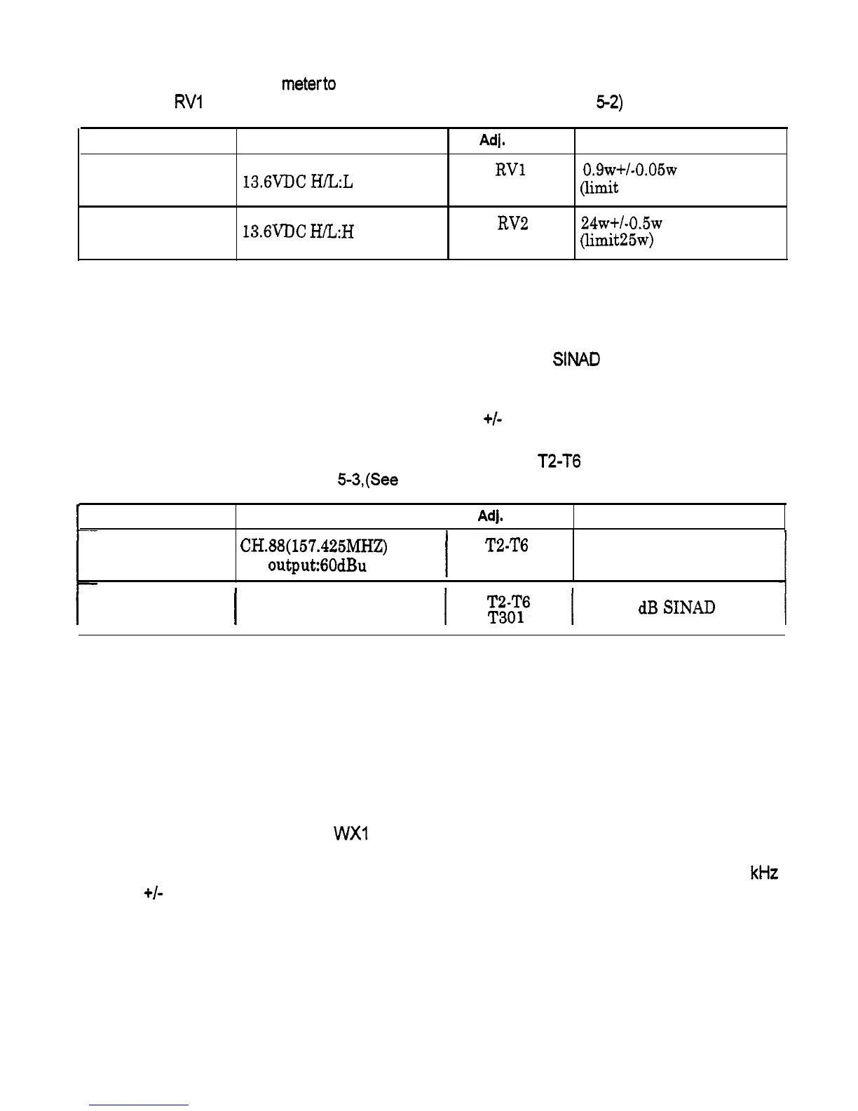
5.3.4 Power Output Adjustment (TRANSMITTER)
1) Connect an RF power meterto the antenna connector through the coupler.
Key to transmit and
adjust
RVI
and RV2 on the main PCB as shown in Table 5-2. (See Fig.
5-2)
Sequence Condition
1
13.6VDC
H/‘L:L
2
13.6VDC
H&H
Ad].
Point
Target Power
RVl
o.gw+/-0.05w
LOW
Power
(limit
1.0 w)
RV2
24w+/-0.5~
High Power
(limit25w)
Table 5-2
5.3.5 RF Sensitivity Adjustment (RECEIVER)
1)
Connect an RF signal generatorto the antenna connector and a SINAD meter to the external
speakerline.
2)
Set the deviation of the RF signal generator to 1 KHz
+/-
3 Hz.
3) Set the output level of the RF signal generator and adjust T2-T6 and T301 on the RF
module as shown in Table 5-3,(See Fig.52).
I
Sequence Conditlon
I
Adj. Point
Target Level
1
CH.BB(157.425MHZ)
SG output:60dBu
I
TZ-T6
T301
Max.Sensitivity
2
I
CH.WXO
SG output:-6dBu
I
Eii6
I
Over 12
dB
SINAD
Table 5-3
5.3.6 Weather Alert Frequency Adjustment (RECEIVER)
1) Connect an RF signal generatorto the antenna connector
Set the RF signal generator as follows:
. Frequency:
162.550 MHz with no modulation
l Output level: 60dBu
2) Select the weather channel
WXI
.
3)
Connect a frequency counter to TP3 on the MAIN PCB and adjust VR4 to obtain 1050 kHz
+/- 5 Hz on the frequency counter. (See Fig. 5-2)
24
 Loading...