EasyManua.ls Logo

Raymarine RAY 210VHF User Manual

Raymarine RAY 210VHF
76 pages
To Next Page IconTo Next Page
To Previous Page IconTo Previous Page
Page #32 background imageLoading...
Page #32 background image
20
MEM (Memory): will appear on the LCD display to show the operator that the
displayed channel has been programmed into the Select Scan memory.
SCAN (All Scan): will appear on the LCD display when the radio is in the All
Scan mode.
WX (Weather): will appear on the LCD display when the radio is in the Weather
mode.
TX (Transmit): will appear on the LCD display when the microphone push-to-
talk switch has been pressed and the transmitter circuits are providing a signal to
the antenna.
1W (1 Watt, Low Power Setting): will appear on the LCD display when the
transmitter output power has been set to Low Power (1 Watt), or when a low
power channel has been selected using the channel selector knob.
F (Function): will appear on the LCD display when the [FUNC] key has been
pressed to operate a secondary key function. The secondary key functions are as
follows : SCAN, 1/25, DWX, MEM, and INTL.
LCD Bar Indicator: In the transmit mode, the 7 bars indicate transmitter
conditions. During low power transmit (1W), 3 bars will be displayed
continuously and a fourth bar will indicate modulation. During high power
transmit (25 W), 6 bars will be lit continuously and seventh bar will indicate
transmit modulation.
V (volt) : The DC supply voltage to the RAY210 will appear on the LCD
display for 5 seconds when the [VOLT] key is pressed.
CHANNEL #: The selected channel number will appear on the LCD display
when a communication, distress, or weather channel is selected by the operator.
Channel numbers will be displayed in two digits (01-88) for U.S A and INTL
channels as follows:
01 88
Weather channels WO to W9 are displayed in a single digit (0-9) on the LCD
display as follows:
0 9

Table of Contents

Question and Answer IconNeed help?

Do you have a question about the Raymarine RAY 210VHF and is the answer not in the manual?

Raymarine RAY 210VHF Specifications

General IconGeneral
BrandRaymarine
ModelRAY 210VHF
CategoryMarine Radio
LanguageEnglish

Summary

Purpose and Important Notice

Important Notice

Crucial disclaimer about device accuracy and user responsibility for navigation.

SECTION 1 INTRODUCTION

General Overview

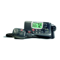
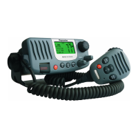
Introduction to the RAY210 marine radiotelephone and its capabilities.

Equipment Features

Lists the main built-in features and capabilities of the RAY210 unit.

Specifications

Details the electrical and mechanical specifications of the RAY210.

SECTION 2 INSTALLATION

Unpacking and Inspection

Instructions for safely unpacking and inspecting the RAY210 unit.

Equipment Supplied

Lists all standard equipment included with the RAY210 model.

Planning the Installation

Guidelines for choosing an optimal and safe installation location.

Mounting Options

Describes various methods for mounting the RAY210 unit.

Electrical Connections Overview

Details on making proper power and speaker connections.

DC Power and Speaker Connections

How to connect the DC power and external speaker cables.

External Speaker Connections

Specific instructions for connecting an external speaker.

Antenna Connections

Guidance on connecting the VHF antenna to the unit.

Antenna Mounting Suggestions

Recommendations for optimal VHF antenna placement.

Grounding

Procedures for properly grounding the RAY210 unit.

SECTION 3 OPERATIONS

Introduction to Operations

Overview of the RAY210's transmission and reception capabilities.

Controls and LCD Display

Detailed explanation of the RAY210's controls and LCD display elements.

Operating Controls

Description of each physical control button and its function.

LCD Display Indicators

Explanation of the various characters and symbols displayed on the LCD.

Operating Procedures Overview

Step-by-step guide for using the RAY210's various functions.

Basic Operating Procedures

Covers power on, volume, squelch, channel selection, and transmit.

Advanced Operating Modes

Covers international frequencies and weather channel selection.

SECTION 4 TECHNICAL DESCRIPTION

Receiving Circuit Operation

Explanation of the internal circuits involved in receiving signals.

Transmitting Circuit Operation

Explanation of the internal circuits involved in transmitting signals.

PLL Circuit Operation

Description of the Phase Lock Loop circuit's function and operation.

SECTION 5 MAINTENANCE

General Maintenance Information

Guidance on contacting support and general care.

Contacting Raymarine Technical Support

Contact details for technical assistance and service inquiries.

Preventative Maintenance

Recommended monthly procedures to ensure optimal performance.

Alignments and Service

Procedures for verifying and adjusting performance parameters.

Test Equipment and Setup

Lists necessary equipment and test setup for service.

PLL Adjustment

Steps for adjusting the PLL circuit for transmitter/receiver.

Transmitter Adjustments

Procedures for adjusting frequency and modulation.

Power Output and RF Sensitivity Adjustment

Steps for adjusting power output and receiver sensitivity.

Weather Alert Adjustment

Procedure for adjusting the weather alert frequency.

Troubleshooting Guide

A chart to help diagnose and resolve common unit issues.

Master Reset Procedure

Instructions for performing a master reset to clear problems.

SECTION 6 PARTS LIST & DRAWINGS

Parts List

Comprehensive list of all electronic components and their symbols.

Assembly Drawing

Exploded view showing how the RAY210 unit is assembled.

Schematic Diagrams

Detailed circuit diagrams for RF and CPU PCBs.

SECTION 7 APPENDIX

VHF Marine Channel Usage and Licensing

Guide to marine VHF channel usage and FCC licensing requirements.

Related product manuals