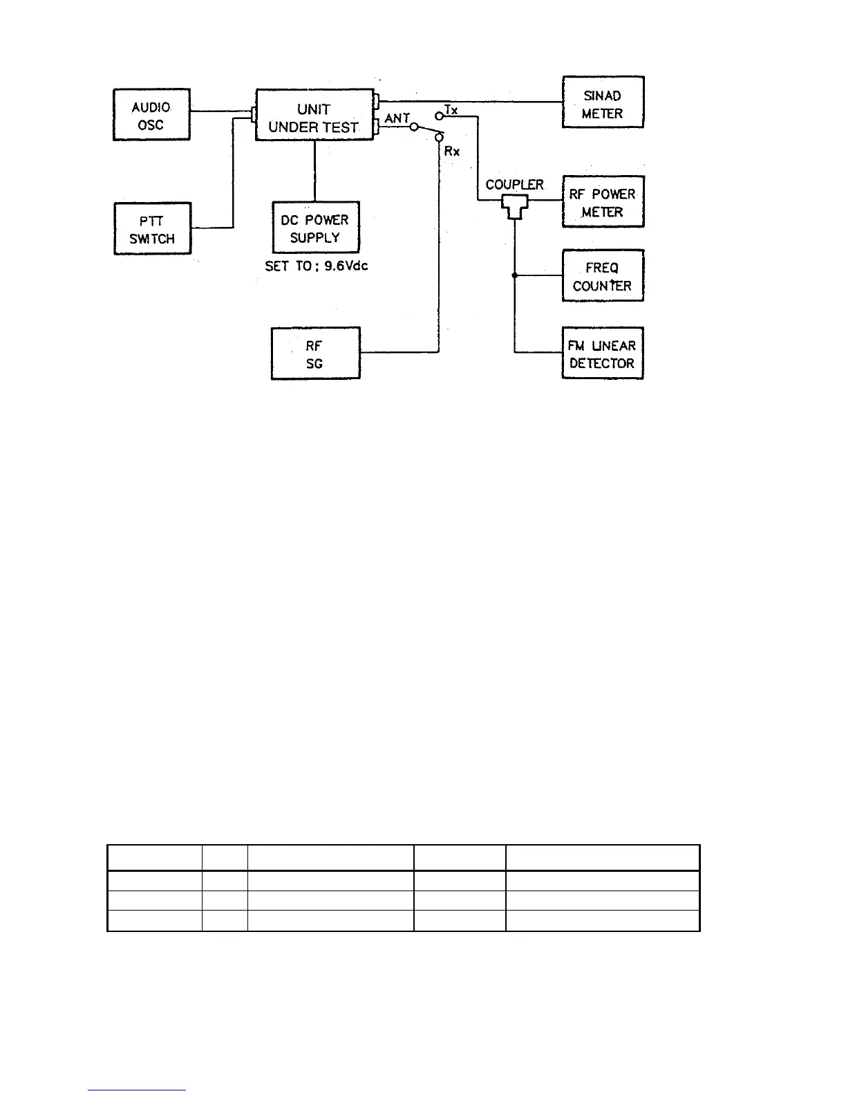
Figure 5-1 Test Setup
5.3.1 Test Equipment
1. DC Power Supply (20V.10A) set at 13.6Vdc
2. RF Power Meter (40W.50 ohm, 150-200MHz)
3. RF signal Generator (50 ohm Output, 150-200MHz)
4. FM Linear Detector (FMLD) or Deviation Monitor 150-200 MHz
5. Frequency Counter
6. Digital Voltmeter
7. Oscilloscope (any oscilloscope accurate for audio signal tracing)
8. SINAD Meter
9. Distortion Meter
10. Toggle Switch (for use as a PTT switch)
11. Coaxial Switch for TX/RX Antenna switching
5.3.2 PLL Adjustment (TRANSMITTER/RECEIVER)
1. Connect the power supply (13.6V, 10A) to the power line and the PTT
switch to the microphone terminal.
2. Connect digital voltmeter or high impedance tester (positive lead to TP2,
negative to ground) and adjust CV2, CV3 on the RF module as shown in
Table 5-1.
Sequence Item Condition Adj. point
Adj. volt.
1 TX transmit CH1 6 CVS 3.5±0.1Vdc
2 RX receive CH1 6 CV2 2.5±0.1Vdc
3 RX receive CH WXO ----- check for 5.5 ±0.3Vdc
Table 5-1
 Loading...