3.4Radarscannerpowerconnections
Radarscannerpowerrequirements.
Thedigitalradarsystemisintendedforuseonships’DCpower
systemsoperatingfrom12to24VoltsDC.
•AllpowerconnectionsmustbemadeviatheVCM100Voltage
ConverterModule.
•TheradarscannermustNOTbeconnecteddirectlytoabattery.
•TheradarscannermustbeconnecteddirectlytotheVCM100
only.
•OnlyoneradarscannermustbeconnectedperVCM100unit.
EachradarscannerinyoursystemrequiresadedicatedVCM100
unit.
•Thepowerconnectionbetweentheradarscannerandthe
VCM100mustbeviaanofcialRaymarinepoweranddatadigital
cable(purchasedseparately).
•DoNOTcutandre-joinanypartofthepoweranddatadigital
cable.Arangeofcablelengthsandcableextensionsisavailable
forlongercableruns.
•TheradarscannermustbeconnectedtothePOWEROUT
terminalsoftheVCM100.
•Thescreen(drain)strandsoftheradarscanner’spoweranddata
digitalcablemustbeconnectedtooneoftheVCM100SCREEN
terminals.
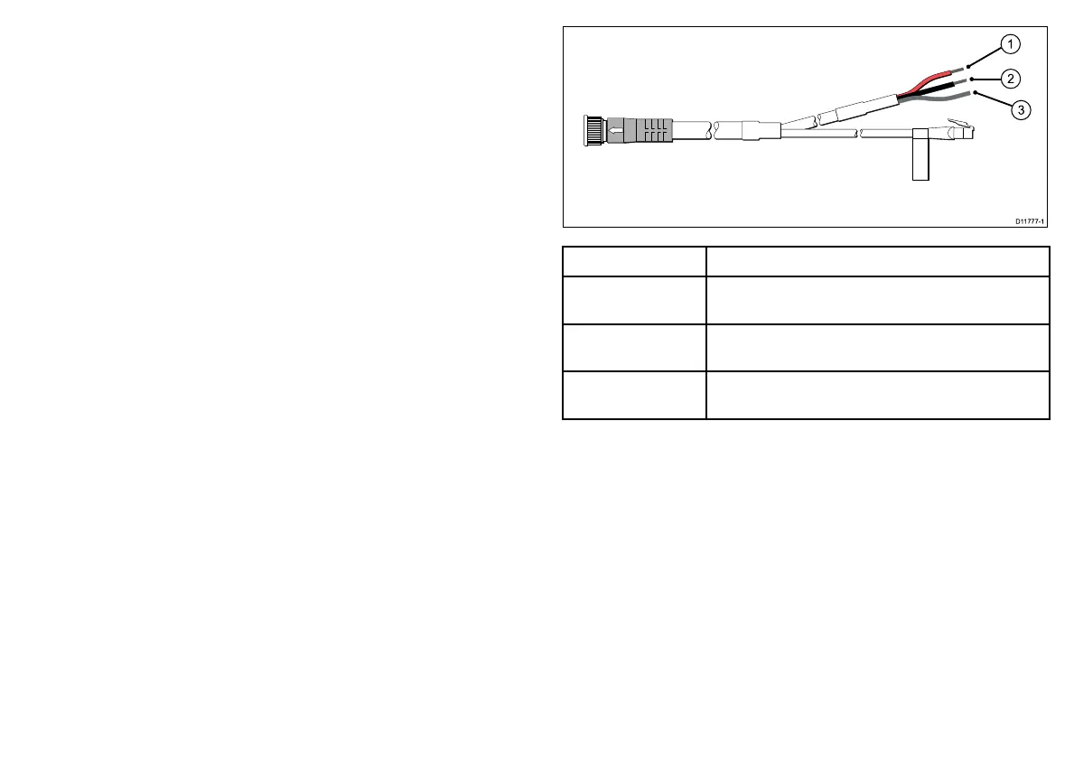
Thefollowingdiagramillustratesthepowerconnectionsofthe
poweranddatadigitalcable.
ItemDescription
1
Redwire—connecttothepositivePOWEROUT
terminaloftheVCM100.
2
Blackwire—connecttothenegativePOWEROUT
terminaloftheVCM100.
3
Screen(drain)strands—connecttooneofthe
SCREENterminalsoftheVCM100.
Cablesandconnections
21
 Loading...