3.11Circuitbreakerandfuseratings
Batteryisolatorswitch,thermalbreaker,andfuseratings.
AllpowerconnectionsbetweentheVCM100anditspowersource
mustbeprotectedbyathermalcircuitbreakerorfuse,ttedclose
tothepowerconnection.Theconnectionfromtheoutputofthe
VCM100tothedigitalradardoesnotrequireafuseorcircuitbreaker.
Ifyoudonothaveathermalcircuitbreakerorfuseinyourpower
circuit(ttedtotheDCdistributionpanel,forexample),youMUSTt
anin-linebreakerorfusetothepositivewireofthepowercable.
Thefollowingtableprovidessuitableratingsforbatteryisolator
switches,circuitbreakers,andfuses.
Power
supplyDevice4kWscanner
12kW
scanner
Isolatorswitch30amps
(minimumrating)
30amps
(minimumrating)
Thermalbreaker15amps15amps
12volt
Fuse20amps20amps
Isolatorswitch15amps
(minimumrating)
15amps
(minimumrating)
Thermalbreaker8amps8amps
24volt
Fuse10amps10amps
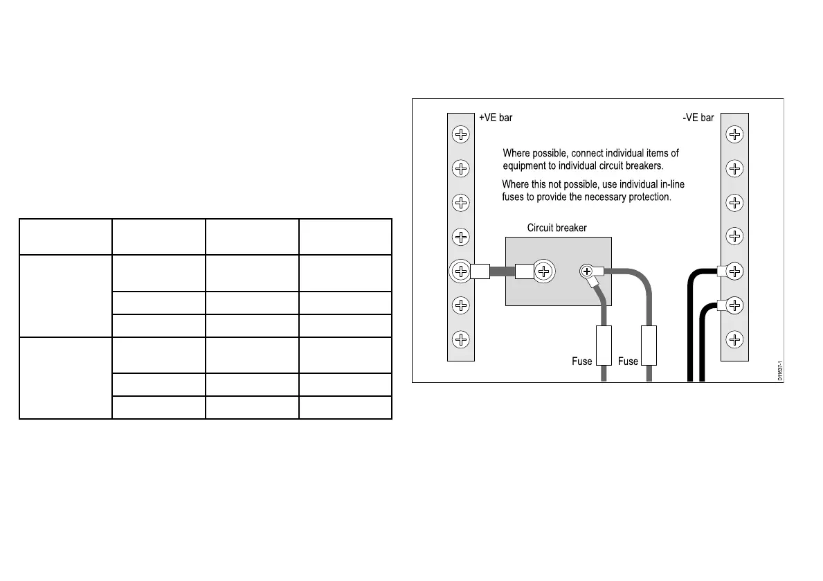
3.12Sharingabreaker
Wheremorethan1pieceofequipmentsharesabreakeryoumust
provideprotectionfortheindividualcircuits.E.g.byconnectingan
in-linefuseforeachpowercircuit.
D11637-1
+VE bar
Circuit breaker
FuseFuse
-VE bar
Where possible, connect individual items of
equipment to individual circuit breakers.
Where this not possible, use individual in-line
fuses to provide the necessary protection.
28
HDandSuperHDDigitalOpenArrayInstallationinstructions
 Loading...