ItemDescription
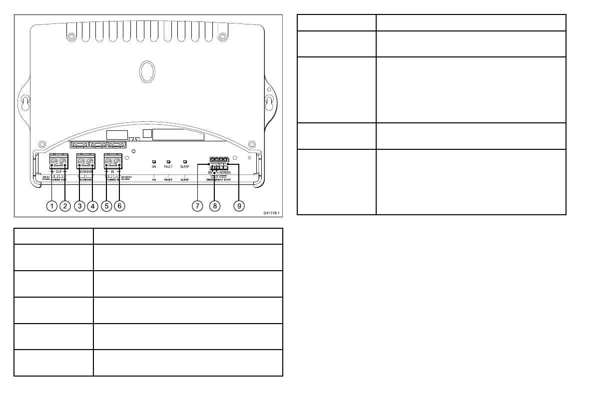
1
POWEROUT(Positive)—connecttotheREDwireof
thepoweranddatadigitalcable.
2
POWEROUT(Negative)—connecttotheBLACKwire
ofthepoweranddatadigitalcable.
3
SCREEN—connecttothebarescreen(drain)strands
ofthepoweranddatadigitalcable.
4
SCREEN—connecttoyourvessel’sRFground
system.
5
POWERIN(Positive)—connecttothepositiveterminal
oftheDCdistributionpanelorbatteryisolatorswitch.
ItemDescription
6
POWERIN(Negative)—connecttothenegative
batteryterminal.
7
EMERGENCYSTOP(Switch)—ifyouhavethe
optionalVCM100emergencystopbutton,removethe
wirebridginglinkfromtheVCM100EMERGENCY
STOPterminals,andconnecttheemergencystop
buttonSWITCHwiretotheVCM100EMERGENCY
STOPSWITCHterminal.
8
EMERGENCYSTOPwirebridginglink—onlyremove
ifttingtheoptionalemergencystopbutton.
9
EMERGENCYSTOP(Screen)—ifyouhavethe
optionalVCM100emergencystopbutton,removethe
wirebridginglinkfromtheVCM100EMERGENCY
STOPterminals,andconnecttheemergency
stopbuttonSCREEN(drain)wiretotheVCM100
EMERGENCYSTOPSCREENterminal.
26
HDandSuperHDDigitalOpenArrayInstallationinstructions
 Loading...