3
QUICK USER GUIDE
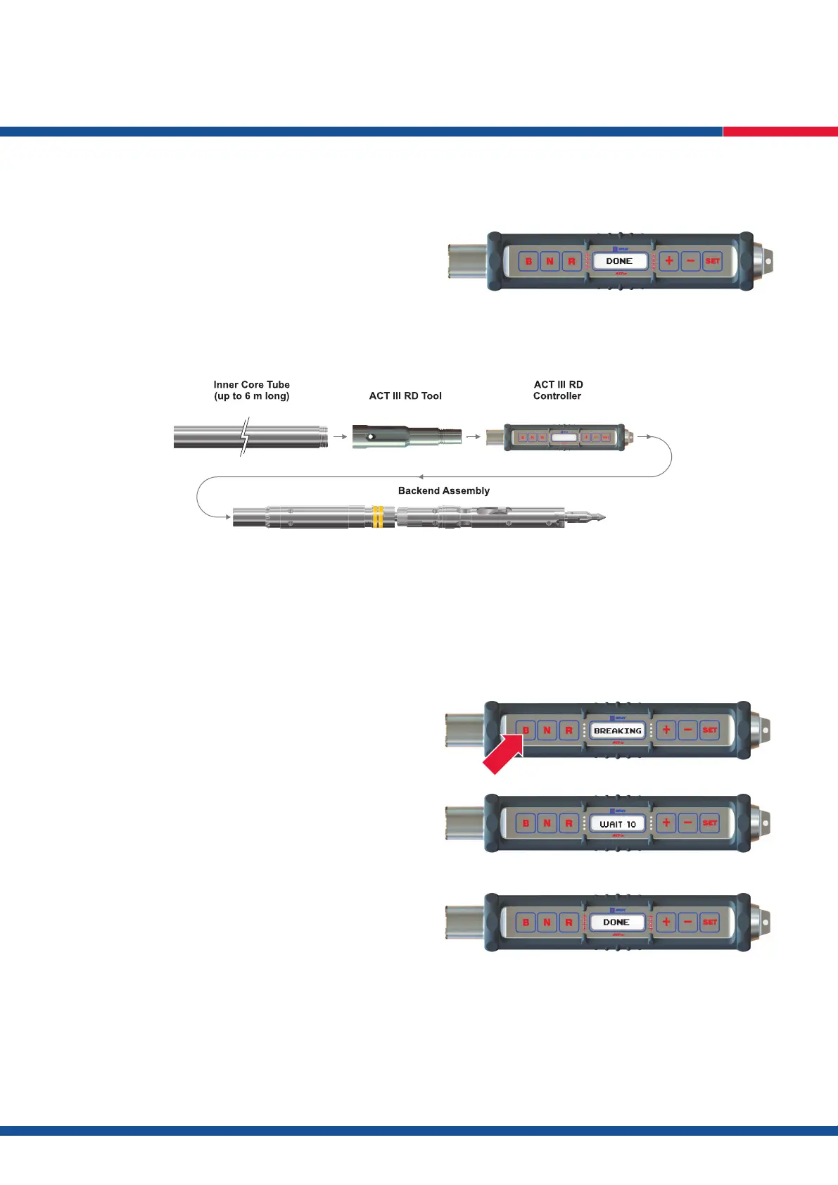
DONE will then show on the LCD display followed by a beep and ash of
the red LEDs (Fig. 7).
The ACT III RD orientation tool is now activated and synchronised to the
controller and will record orientation data every minute.
3.5. Remove the ACT III RD controller from the tool, reattach the ‘Top
Cap’ and ‘Back End’ assembly (Fig. 8) and tighten as per standard
drilling practice.
The inner tube assembly can now be lowered into the rod line as per
standard drilling practice and the drilling process can commence.
4. Breaking
N.B. If using the optional download function please refer to Section 2, on page 6, of this manual for further instructions on how to enter the hole depth.
Before the core can be broken off bottom at the end of the coring run, the bottom of hole orientation MUST be recorded on the ACT III RD controller
as follows:
4.6. Stop all rotation and thrust of the drill rods – DO NOT BREAK OFF BOTTOM.
4.7. Press the B button on the ACT III RD controller and hold down for 5 seconds, BREAKING will display on the control panel (Fig. 9).
4.8. WAIT will next appear on the LCD screen with a countdown display (Fig. 10).
The core CAN NOT be broken off bottom until the countdown timer
reaches 0 seconds.
The controller will ash the red LEDs and DONE will appear on the
LCD display screen (Fig. 11) when it is safe to break the core off bottom.
N.B. If you wish to cancel the break, this can be done by pressing N but
MUST be done before the countdown reaches 0 seconds.
4.9. The core can now be broken off bottom.
N.B. Rotation should NOT be used to assist core breaking.
5. Initialise Second ACT III RD Tool
The second ACT III RD can now be initialised following the steps in
Section 1, item 3.
N.B. The second tool can only be initialised after a break has been
recorded on the rst tool.
Fig. 9
Fig. 10
Fig. 11
Fig. 7
Fig. 8
Top Cap
Inner Tube
 Loading...