Section 2: Depth and Dip Display Function
ACT III RD
rapid descent core orientation tool
6
1. Breaking – Using the Depth Display Function
N.B. Steps 1–3 below should be followed if using an ACT III RD tool that has the Depth and Dip display function enabled.
Before the core can be broken off bottom at the end of the coring run, the bottom of hole orientation MUST be recorded on the
ACT III RD Controller as follows:
1.1. Stop all rotation and thrust of the drill rods – DO NOT BREAK OFF
BOTTOM.
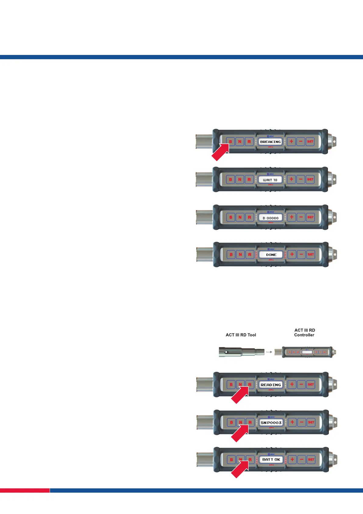
1.2. Press the B button on the ACT III RD controller and hold down for 5
seconds, BREAKING will display on the control panel (Fig. 21).
1.3. WAIT will appear on the LCD screen with a countdown display
(Fig. 22). The core CAN NOT be broken off bottom until the
countdown timer reaches 0 seconds.
The controller will ash the red LEDs.
1.4. The screen will display D 00000 (Fig. 23).
1.5. Press SET then the + or – button to adjust the depth number value.
1.6. Press SET to scroll to the next number and use the + or – buttons
to change the number value.
1.7. After the desired depth has been entered press B once more and
DONE will appear (Fig. 24).
N.B. There is a 1 minute time limit to enter the depth – if no buttons are
pressed the controller will save the depth reading that is on the display
screen 1 minute after the last button was pressed.
1.8. The core can now be broken off bottom.
N.B. Rotation should NOT be used to assist core breaking.
2. Initialise Second ACT III RD Tool
The second ACT III RD can now be initialised following the steps in Section 1.
N.B. The second tool can only be initialised after a break has been recorded on the rst tool.
3. Retrieving Orientation from ACT III RD Using Dip and Depth Display Function
With the core inner tube assembly returned to the surface the bottom of hole
orientation can now be retrieved from the ACT III RD tool and transferred to the core
using the same controller.
3.1. Remove the ‘Top Cap’ from the ACT III RD to expose the magnetic Infra Red Port
and insert the ACT III RD Controller (Fig. 25).
3.2. Press and hold the R button for 5 seconds – the LCD display will ash
READING (Fig. 26) followed by the ACT III RD tool serial number and
then BATT OK.
N.B. The R must be pressed for the full 5 seconds in order to view the
screens (Fig. 26).
N.B. BATT OK will still be displayed after you stop pressing the R button.
3.3. While BATT OK is still displayed on the LCD screen press R again –
the depth that was entered during the Break (B) will now be displayed,
e.g. D 00000 (Fig. 23).
Fig.21
Fig. 22
Fig. 23
Fig. 24
Fig. 25
Fig. 26
 Loading...