5
QUICK USER GUIDE
7. Transferring Orientation to the Core
7.1. Before removing the ACT III RD controller the bottom of hole orientation should be transferred to
the core using either the UNDER (Fig. 18) or OVER (Fig. 20) method.
N.B. The best method to use is determined by the tube racks. If the racks are shorter than the inner tube
then the UNDER method can be used. If the racks are longer than the inner tube then the OVER method
may be more practical.
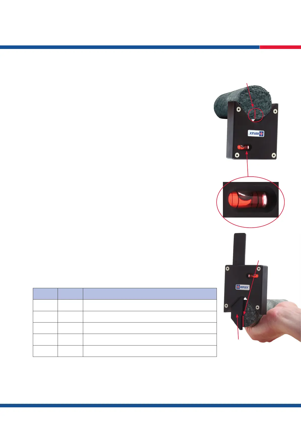
Under Method:
i. Ensure that bottom of hole orientation is indicated on the ACT III RD Controller (Fig. 17)
ii. Place the ACT III RD Marking Jig under the core lifter case (Fig. 18)
iii. Level the marking jig by using the levelling bubble (Fig. 19)
iv. Mark the bottom of the core (Fig. 18).
N.B. If the core is inside the lifter case the marking jig can be tilted or the lifter case marked and then the
orientation transferred to the core using a straight edge.
7.2. If there is not suf cient overhang of the core lifter case then the OVER method should be used to
mark bottom of hole orientation.
Over Method:
i. Ensure that bottom of hole orientation is indicated on the ACT III RD Controller (Fig. 17)
ii. Place the ACT III RD Marking Jig on top of the core lifter case (Fig. 20)
iii. Level the marking jig by using the spirit level (Fig. 19)
iv. Select the core grade, e.g... NQ*, and extend the ‘marking blade’ down to the bottom of the
lifter case (Fig. 20)
v. Using the marking blade as a guide mark the bottom of the core.
8. Cancelling a Tool
In the event an ACT III RD unit cannot be retrieved from the drilling barrel that particular tool must be
cancelled from the ACT III RD Controller before a third replacement tool can be introduced as follows.
8.1. Press and hold B and SET on the ACT III RD Controller to initialise the display function – the
Controllers individual serial number will be displayed.
8.2. Press R repeatedly to scroll through the menu until the active tools serial number is displayed,
e.g. CX 00021.
8.3. Press SET to cancel the orientation tool.
Press Display
B and SET SN 12345 Press B and SET simultaneously displays the control unit serial no.
R BATT OK Displays control unit battery status: OK or LOW.
R CX 00021 Displays serial no. of rst active tool. Press SET to cancel survey.
R CX 00027 Displays serial no. of second active tool. Press SET to cancel survey.
N or B Press N or B during display cycle to exit and power off.
* Q®is a registered trademark of Boart Longyear that refers its Q® Wireline System. The use of the Q mark herein is not intended to equate the Q mark with a particular
hole size but rather to indicate that Re ex’s products and services are designed and intended to be used with Boart Longyear’s Q® Wireline System, as well as other
wireline systems available in the industry that are comparable to that of the Q® Wireline System.
Fig. 18
core orientation mark
Fig. 19
Fig. 20
marking blade
core orientation mark
 Loading...