Use
22
A9MA03EN 02/2012
Operating Modes
Introduction
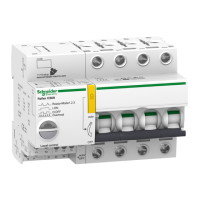
All versions of the Reflex iC60 integrated control circuit breaker, with and without Ti24 interface, have 2
control inputs (Y1 and Y2). In addition, the version with Ti24 interface has an additional control input (Y3)
dedicated to control from a PLC.
The Reflex iC60 version without Ti24 interface has 2 operating modes: mode 1 and mode 2. Mode 1 is
the default mode.
The Reflex iC60 version with Ti24 interface has 3 operating modes: mode 1, mode 2 and mode 3. Mode
3 is the default mode.
Reflex iC60 integrated control circuit breaker functions
The following table describes the available functions according to the type of Reflex iC60 circuit breaker.
Mode Function Input/Output A9C5••••
(without
Ti24)
A9C6••••
(with Ti24)
1 Local closing control on rising edge and opening control on
falling edge
Y1 √√
Local one-shot closing and opening control Y2 √√
Centralized closing control on rising edge and opening
control on falling edge (conforming to standard IEC 61131-2)
Y3 – √
2 Local opening control on rising edge, latched at high state
(state = 1) to inhibit local one-shot closing and opening
control
Y1 √√
Local one-shot closing and opening control Y2 √√
Centralized closing control on rising edge and opening
control on falling edge (conforming to standard IEC 61131-2)
Y3 – √
3 Centralized control enabled (Y1 = 1) or centralized control
inhibited (Y1 = 0)
Y1 √√
Local one-shot closing and opening control Y2 √√
Centralized closing control on rising edge and opening
control on falling edge (conforming to standard IEC 61131-2)
Y3 – √
1, 2, 3 Indication of the position (open/closed) of the circuit breaker
contacts
O/C – √
Indication of the position of the circuit breaker handle. auto/OFF – √

 Loading...