EasyManuals Logo
Home>Renesas>Microcontrollers>RA Series

Renesas RA Series User Manual

Renesas RA Series
38 pages
To Next Page IconTo Next Page
To Previous Page IconTo Previous Page
Page #23 background imageLoading...
Page #23 background image
Renesas RA Microcontrollers EK-RA6M2 v1 – User's Manual
R20UT4578EU0102 Rev.1.02 Page 20 of 32
Jul.29.20
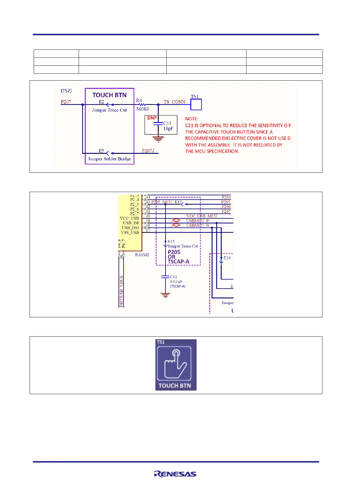
Table 12. Evaluation Kit Capacitive Touch Button Sensor
Designator
Function
MCU Control Port
MCU Pin
TS1
Capacitive Touch Button
U1 P207
U1-41
TSCAP-A
TSCAP Support
U1 P205 (TSCAP-A)
U1-43
Figure 21. Capacitive Touch Button Circuit
Figure 22. Capacitive Touch TSCAP Circuit
Figure 23. Capacitive Touch Button on the Evaluation Kit (Top side)
5.5 Pin Headers
The Pin Headers, J1, J2, J3, and J4, provide access to all Main MCU interface signals, and to voltages for all
Main MCU power ports.
On the EK-RA6M2 board, 40 pins of the pin headers are set aside for fixed function assignment. These
pins are odd-numbered pins of J1 and even-numbered pins of J2.

Other manuals for Renesas RA Series

Questions and Answers:

Question and Answer IconNeed help?

Do you have a question about the Renesas RA Series and is the answer not in the manual?

Renesas RA Series Specifications

General IconGeneral
BrandRenesas
ModelRA Series
CategoryMicrocontrollers
LanguageEnglish

Related product manuals