RL78/G13 Safety Function (Frequency Detection)
5.8.3 I/O Port Setup
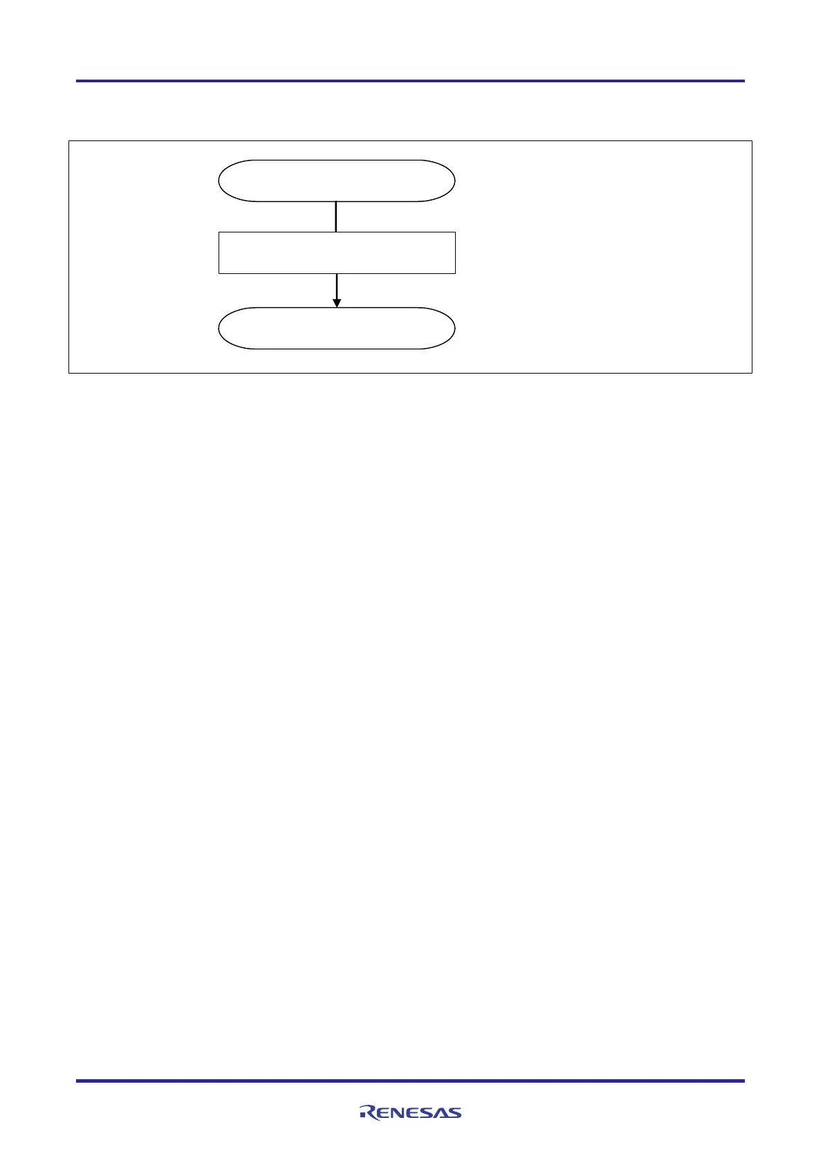
Figure 5.4 shows the flowchart for I/O port setup.
R_PORT_Create
Set up I/O port for LED
Set P62 and P63 to output mode
return
PM6 register
F0H
P6 register
0CH
Figure 5.4 I/O Port Setup
Cautions: 1. Refer to the section entitled "Flowcharts" in RL78/G13 Initialization Application Note (R01AN0451E)
for the configuration of the unused ports.
2. Provide proper treatment for unused pins so that their electrical specifications are met. Connect each of
any unused input-only ports to V
DD
or V
SS
via a separate resistor.
R01AN0956EJ0100 Rev. 1.00 Page 27 of 70
Feb. 27, 2012

 Loading...


