EasyManua.ls Logo

Resource Data Management PR0750-MOB User Manual

Resource Data Management PR0750-MOB
21 pages
To Next Page IconTo Next Page
To Previous Page IconTo Previous Page
Page #13 background image
Revision 1.1 Page 13 of 21
Warning
Please Note
The specifications of the product detailed on this
Set-Up Guide may change without notice. RDM
Ltd. shall not be liable for errors or for incidental
or consequential damages, directly and indirectly,
in connection with the furnishing, performance or
misuse of this product or document.
Ensure that all power is
switched off before
installing or maintaining
this product
Mercury 2 & Intuitive Mobile Controller User Guide
www.resourcedm.com
Relay and screen states during defrost
State:
Pump Down
Defrost Min
Defrost Max
Drain Down
Fan Delay
Recovery
Screen:
DEF
DEF
DEF
DEF
DEF
REC
Def LED:
On
On
On
Off
Off
Off
RLY 1 Comp A (Defrost set to gas)
Off
On
On
Off
On
On
RLY 1 Comp A (Defrost set to electric)
Off
Off
Off
Off
On
On
RLY 1 Comp A (Defrost set to elec/cln)
Off
Off
Off
Off
On
On
RLY 4 Comp B
Off
Off
Off
Off
On if Reqd
On if reqd
RLY 5 Defrost Relay
Off
Off/Cycles*
On
Off
Off
Off
RLY 3 Lights relay (Timer channel On)
On
On
On
On
On
On
RLY 2 Fans (On in DF)
On
On
On
On
Off
On
RLY 2 Fans (Off in DF)
Off
Off
Off
Off
Off
On
*The defrost relay will cycle around the termination setpoint during defrost min if defrost type is set to elec/cln, otherwise it will be off.
Defrost Type (P-91)
If P-91 is set to gas, compressor A is switched on for the duration of the defrost cycle.
Defrost Termination
Defrost termination will be when the temperature parameter "def terminate" has been reached on the "defrost termination" probe. If the
"defrost termination" probe is not fitted then the air off probe will be used.
Fan Delay after Defrost
The fans will come back on when: -
The fan delay time has elapsed if the "fan delay mode" is set to time
Or If the fan delay mode is set to "temp", the fans will come on when the defrost termination probe reaches the fan delay set point,
or on the time parameter, whichever occurs first.
If the "defrost termination" probe is not fitted, the fans will come on when the air off probe reaches the control set point (If fans are
selected as "on during defrost")
Network Configuration
The final section to setup is the network address. In all instances, this must be done before the controller is plugged into the site network.
The controllers have an auto-initialise function, which will automatically log the device onto the site network. If the wrong address has
been entered onto the network, you will have to reset the controller address by setting the address to 00-0, and then re-enter the correct
address. (You may have to deregister the wrong address from the home system as well).
When logging a Mercury or Intuitive Mercury with an RS232 interface onto a network you must first connect the controller to a
communications module, this is either a 485 Legacy, RDM Wireless Mesh system, IP Futura or Mercury Switch. When using an Intuitive
Mercury controller, the controller has to have the correct network card fitted (see “compatible network interfaces”). For connection to a
Mercury Switch (Hub) or an external network interface, the standard fitment RS232 network card is utilized.
RS485 Legacy module / Intuitive Internal RS485 Network card
Connecting an RS485 legacy Module or an Intuitive Internal RS485 network card to the controller will govern which set up screens are
made available. Both modules support the “Genus” protocol only.
Display
Option
485t
485 Network Type
485A
485 Address/Name
gAdd
Show underlying network address assigned to controller
rLog
Re-log the controller back onto the network
CLrA
Clear the address/name from the controller
ESC
Exit network menu. N.B. this option must be selected to save any changes made in this menu
The 485t option shows a value representing the network type. The possible values are:
Value
Network Type
1
Genus compatible (all versions)
2
RDM Wireless Mesh System (Wireless Mesh)
The 485A option shows a value representing either the name of the controller in a Genus compatible or Wireless Mesh network.

Table of Contents

Question and Answer IconNeed help?

Do you have a question about the Resource Data Management PR0750-MOB and is the answer not in the manual?

Resource Data Management PR0750-MOB Specifications

General IconGeneral
Communication ProtocolModbus RTU
Power Supply24 VDC
MountingDIN Rail
Input Voltage24 VDC
ProtectionIP20
Dimensions90mm x 70mm x 60mm
Weight200g

Summary

The Mercury & Intuitive Range

Variants

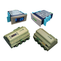
Describes different controller models available, including Mercury Mk2 and Intuitive Mercury types.

Compatible Displays

Lists compatible display units for Mercury and Intuitive Remote Display Controllers.

Configuration Options

Details the two available controller configuration options: Integral controller HT and LT.

Compatible Network Interfaces

Lists network connection modules for controllers, including IP, RS485, and Wireless Mesh.

Front Display Features

LED Indicators

Explains the function of the status LEDs on the front panel for Cooling, Fans, Lights, and Defrost.

Control Buttons

Describes the function of the front panel keys: Enter, Up, Down, and Defrost.

Main Display

Details the 4-character LED display and its role in showing temperature and status messages.

Connections

Mercury Mk2 6-5E and 6-5M

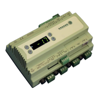
Details the input/output and communication port connections for the Mercury Mk2 controller.

Intuitive Mercury Controller Options

Network Expansion Options

Lists optional internal network cards for the Intuitive Mercury controller (IP, RS485, Wireless Mesh).

Ordering Information

Explains the part numbering scheme for ordering controllers with specific hardware configurations.

Input and Output Allocation

Input/Output Table

Details the functions assigned to controller inputs and outputs based on type.

Switched Resistor Values

Information on resistor values required for specific input functions like Plant Fault.

Setting up the Controller

Access Methods

Outlines the different ways to access controller settings: front buttons, PC, or network.

Setup via Front Buttons

Step-by-step guide for configuring the controller using its front panel buttons.

Setup Function Menu

Menu Navigation and Options

Lists and describes the available options in the setup menu, such as IO, PA/A, Unit, and nEt.

Recommended Set-up Method

Real Time Clock (rtc) Setup

Steps to configure the controller's internal clock, including date and time settings.

Controller Type (tyPE) Setup

Steps to select the controller's type, either High Temperature (HT) or Low Temperature (LT).

Parameters (PArA) Setup

Guide to accessing and modifying controller parameters via the setup menu.

Units and Probe Type (Unit) Setup

Steps to set temperature units (Celsius/Fahrenheit) and select probe types.

Parameter Tables

Parameter Reference Table

Lists parameters P-01 to P-44 with their range, step, units, and default values.

Display Function Configuration

Describes how to configure the controller's display format for temperature readings.

Parameter Descriptions

Parameter Explanations

Provides detailed explanations for various controller parameters, covering their function and use.

Defrost and Fan Control Parameters

Explains parameters specific to defrost operation and fan control logic.

Parameter Descriptions (cont.)

Input and Output Function Parameters

Explains parameters related to inputs, outputs, alarms, and probe logging functions.

Parameter Descriptions (cont.)

Lighting and Load Shedding Parameters

Explains parameters for lighting modes, case off, and load shedding functions.

Relay State and Functional Operation

Describes the functional states of relays 1-5 under different operating conditions.

Defrost Operation Details

Relay and Screen States During Defrost

Shows controller states and relay activity during different defrost phases (Pump Down, Min, Max).

Defrost Type (P-91)

Explains the settings for defrost heater type (Electric, Gas) and their effects.

Defrost Termination

Details how defrost cycles are terminated based on probe temperature or settings.

Fan Delay After Defrost

Explains fan behavior following a defrost cycle, based on time or temperature.

Network Configuration

RS485 Network Setup

Guides configuration for RS485 compatible networks, including network type and address.

Network Configuration (cont.)

Wireless Mesh Communication Module

Information on connecting a controller via a Wireless Mesh communication module.

Fast Network Address Reset

Procedure for resetting network addresses and names in the controller.

IP Futura / Internal IP Network Card

Details on configuring IP network cards for the controller.

Network Configuration (cont.)

IP-r Configuration

Steps to configure dynamic IP addressing via DHCP for IP networks.

Mercury Switch

Information on connecting and using the Mercury Switch device for network access.

Input / Output Table Viewing

How to view the current status of inputs and outputs on the controller.

Temperature Monitoring

Max and Min Control Temperature

How to view the highest and lowest control temperatures recorded since last power cycle.

Controller Messages and Alarms

System Status Messages

Lists and explains system status messages and alarms displayed on the controller.

Network Alarms

Lists and explains alarms related to network communication and status.

Modifying Controller States

Specific Controller States

Fans Only Mode

How to set the controller to operate in Fans Only mode.

Case Off Mode

How to set the controller to operate in Case Off mode.

Lights Only Mode

How to set the controller to operate in Lights Only mode.

Probe Offset Adjustment

Remote Control Commands

Product Specifications

Power Requirements

Details the electrical power requirements for both Mercury Mk2 and Intuitive Mercury controllers.

General Specifications

Covers operating temperature, environmental factors, size, safety, and EMC compliance.

Relay Specifications

Details the specifications for the controller's relays, including current, voltage, and type.

Input and Wiring Details

Input Specifications

Describes input resistance and selectable input types for temperature probes.

Switched Resistor Example Wiring

Provides a wiring diagram example for using switched resistors on a probe input.

Installation and Mounting

Panel Cut-out and Clearances

Specifies panel cut-out dimensions and clearance zones for flush mounting the Mercury Mk2.

Mercury Mk2 Dimensions

Provides physical dimensions and diagrams for the Mercury Mk2 controller units.

Installation and Mounting (cont.)

Intuitive Mercury Dimensions

Provides physical dimensions and diagrams for the Intuitive Mercury controller.

Intuitive Mercury Mounting Instructions

Details how to mount the Intuitive Mercury controller onto a DIN rail.

Maintenance and Disclaimers

Cleaning Instructions

Guidance on how to clean the controller's front panel safely.

Disclaimer

Legal notice regarding product specifications, changes, and liability.

Document Information

Document Revision History

Lists revisions and changes made to the user guide document over time.

Related product manuals