56
minal labeled “W2” can be connected
to this terminal to activate the timed
staging feature of this furnace.
Note: Do not apply 24vac to the V/W2
terminal (as with a jumper to R for diag-
nostic purposes) when a non-communi-
cating, modulating thermostat is
installed.
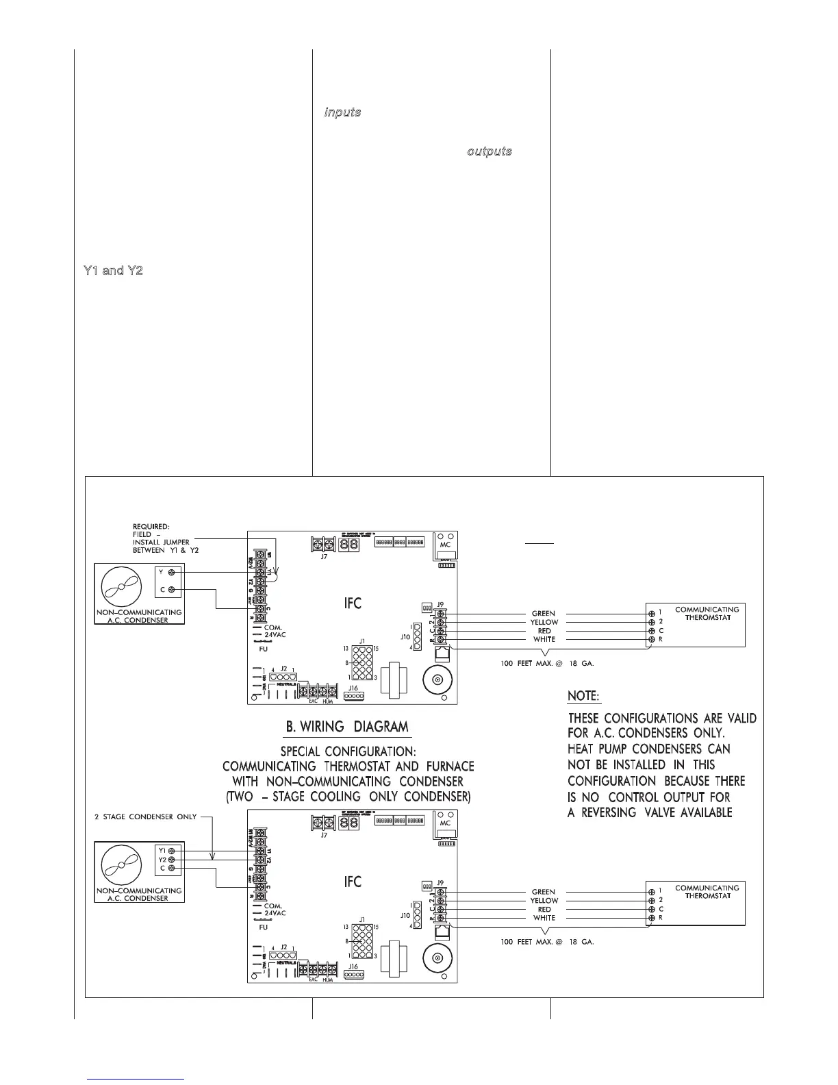
SPECIAL CONFIGURATION
– COMMUNICATING THER-
MOSTAT AND FURNACE
WITH A NON-COMMUNI-
CATING CONDENSER
Y1 and Y2
– These terminals may be
used to connect directly to a non-com-
municating condenser when a commu-
nicating thermostat is installed to the
furnace but a non-communicating con-
denser is installed in the system. While
the optimum configuration is with a
communicating condenser connected
to the network, there may be installa-
tions where this is not desired. In
these cases, the thermostat will be
communicatin
g with the furnace control
and the furnace control will energize
the condenser as necessary (the addi-
tional relays have been added to the
furnace control to allow this operation).
The thermostat connections labeled
“Y1” and “Y2” on the I.F.C. are normally
inputs
to the furnace control to turn on
the blower when they are energized.
However, in this configuration, these
(normally) inputs become
outputs
to
energize the condenser when a cooling
call has been sent from the communi-
cating thermostat.
When this configuration is desired, use
the wiring diagram in Figure 59 to con-
nect the thermostat and condenser to
the furnace control. For single stage
condensers, a jumper must be installed
between Y1 & Y2 at the furnace con-
trol.
NOTE: A heat pump condenser cannot
be installed with this configuration.
There
is no control for the reversing
valve.
24 VAC FROM TRANS-
FORMER (XFORMER) CON-
NECTIONS
These inputs are used to connect
24VAC from the furnace transformer to
the furnace control (I.F.C.).
FUSE (F1)
A three-amp automotive-style (ATC
blade type) fuse is supplied on-
board the furnace control. This fuse
should provide protection from
short-circuits on the control board
and associated 24 VAC wiring.
115 VAC TERMINALS
These terminals supply 115 VAC to
the furnace control from the input at
the junction box of the furnace.
Additionally, spare terminals are pro-
vided for use with electronic air
cleaners and other accessories as
needed (Check the voltage rating of
your equipment.)
INDUCED DRAFT MOTOR
(INDUCER) OUTPUT (J2)
This four-pin Mate-n-Lok style con-
nector is black in color and provides
power to both the high and low
speed inducer outputs. This con-
nector on the IFC has female sock-
ets so that it can not be confused
with the four-pin connector used for
motor control (which has male pins).
FIGURE 59
WIRING DIAGRAM – SPECIAL CONFIGURATION: COMMUNICATING THERMOSTAT AND FURNACE WITH NON-COMMUNICATING CONDENSER
ST-A1115-01, REV. 02
NOTE:
DEHUMIDIFICATION FUNCTION FROM A
COMMUNICATING THERMOSTAT WILL NOT
BE POSSIBLE WITH THIS CONFIGURATION.
 Loading...


