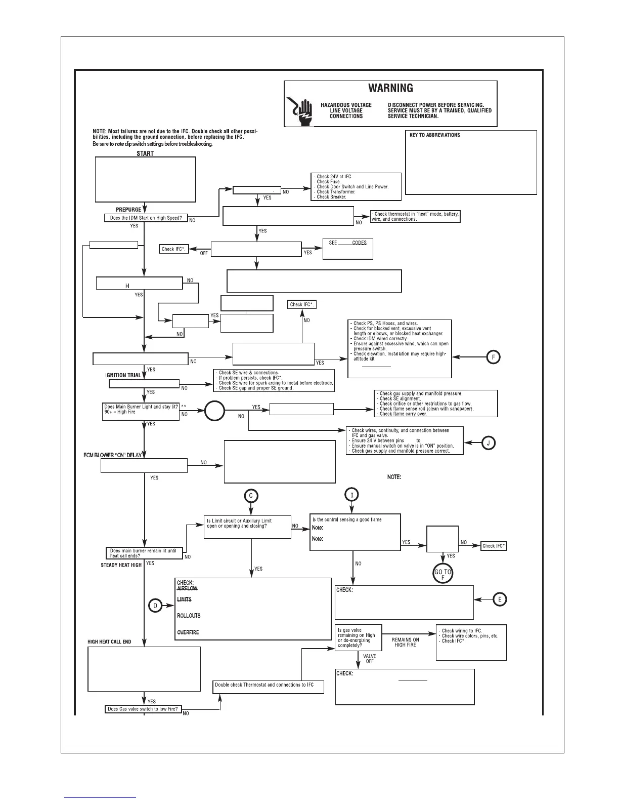
87
FIGURE 82
TROUBLESHOOTING CHART
MODULATING INTEGRATED
FURNACE CONTROL (IFC)
TROUBLESHOOTING GUIDE
ECM = Constant CFM Blowers. (Electronically commutated motor)
TSTAT = Thermostat.
IDM = Induced Draft Motor (or Inducer).
IFC = Integrated Furnace Control (or control board).
PS = Pressure Switch(es).
PFC = Power Factor Correction Choke.
SE = Spark Electrode (s).
SSD = Seven Segment Display of Furnace control
COMM. = Communication.
I&O = Instal
lation & Operation Instructions Manual.
1) Set DIP switches SW2-2 to “OFF” and SW2-3 to
“ON” for test mode - high fire.
2) Set FAN switch to “AUTO” on T-stat.
3) Set thermostat to call for heat (set temp.
differential to greater than 10°F).
4) “H” should be displayed at “SSD’s” and should
Be on steady, if flashing check dip switches
(Item “1”).
For Non-Comm. Systems.
“A capital
is displayed at IFC SSD’S”
Dual SSD’S “ON”
Is thermostat heat call present?
For 24 VAC (Non-Comm. T-stat., is 24 VAC on W1 and/or W2 of
IFC. H or h should be displayed at SSD’S.
Is a fault code displayed at IFC?
(After 10 Sec. a fault code will display anyway)
H or h only
For 1st 10 Sec. only
FAULT
Under ”Troubleshooting”
in I & O Manual
Is a modulating
T-stat connected?
Check “V” signal wires &
connections, replace or
repair as necessary
Check t-stat, replace if
necessary.
(pre-purge) IDM runs for 30 sec. at high speed?
Does IDM Run for 60 Sec. and then off
for five minutes with fault
45, 48 or 57 displayed?
- See FAULT CODES under “Troubleshooting” in
I&O Manual.
J16-4
J16-5 on IFC.
If IFC goes into lockout (”r” will be displayed at SSD’s), shut off
main power to unit, wait 30 seconds then reset power or removed heat
call and re-establish.
- Check all connections between I.F.C. & E.C.M. Motor.
- Check 24v to E.C.M. control (4pin connector, pin 1-4)
- Check Dip switch setting.
- Check P.F.C. choke.
- Check all wiring and connections to P.F.C choke.
- Check fault code display, see
“fault codes” in I & O.
- Check line voltage to motor (115VAC).
Does ECM blower start on high heat
speed 15-20 seconds after burners light?
Note: IFC SSD’s will display “22, 33 or 23”.
?
If good flame is not sensed a fault code
“11” or “13” will be displayed at SSD’s
“12” is low flame sense, furnace should
still operate well.
Fault code
“45”, “46” or
“57” displayed
at SSD’s.
- Check test mode dip switches.
- Make sure test mode has not
expired (1 hour limit).
- Fault codes at IFC SSD - see FAULT CODES under troubleshooting
in I&O manual.
- 24V Between IFC pins J16, Pin 4 & J16, Pin 5 of I.F.C.
- Make sure heat call present at T-stat.
- T-stat wires and connections
Remove heat call by setting T-stat set point below
room temperature. remove power to furnace and open
blower door. Set dip switch SW2-2 to “ON” and SW2-3
to “OFF”. Replace furnace door, reset po
wer to
furnace. Initiate new heat call. Allow heat call to
proceed through blower on delay. The burners drop
from high fire to low (40%) rate and I.B.M. energizes at
low heat CFM.
Check to make sure test mode dip switches are properly set.
- Check all connections between IFC and ECM motor.
- Check 24V to ECM Motor. (low voltage connector, pins 1 & 4)
- Check P.F.C. Choke.
- Check all wiring and connections to P.F.C. choke.
- Check fault code display and see “fault codes” In I & O.
Does I. B. M. energize at low speed?
After Blower on delay, Does IDM switch to low speed
and remain at low speed after switching?
Does furnace continue to operate at low
fire until T-stat satisfied or heat call
removed?
Ensure T-stat not
switching to high fire or
test mode dips witches
not timing out (1 hour
limit)
Fault code displayed?
See FAULT CODES under
troubelshooting in the I & O Manual
Does IDM
Shut off after Twenty Second post purge?
Does I. B. M. shut off after 90 seconds? (plus slew)
Double check - is heat call
completely off at IFC?
** System will attempt to light 4 times. Voltage Is present at gas valve for
only 7 seconds during each ignition trial. System will enter a 1 hour
lockout after 4 attempts.
For Comm. System
Lower case “h”
Capital “H”
2 Stg. or 1 Stg. Non Comm. T-stat
-Check line voltage at I.D.M.
-Check Wires And connections between I.D.M. and I.F.C.
-Ensure line voltage between J2, Pin 1 & J2, Pin 4 of I.F.C. (High IN Output).
-Check I.D.M. Capacitor.
Spark Electrodes (SE) Energize?
See I&O.
Does gas valve remain
energized?
PROBLEM
PERSISTS
- ensure no restrictions, such as dirty filter, blower wheel,
dampers or closed registers, Etc. exist.
- ensure good wire and connections between I.F.C. and all limits.
makes sure limits are not open when circulating air temperature is within a
specific range.
- Ensure rollouts or overtemperature limits do not need to be
reset. make sure no flame rollout in burner compartment due to blocked flue
or heat exchanger or combustion restriction.
- ensure furnace is not overfired (temp rise is above stated
range). Check gas valve, proper orifice size, gas presure
-Grounding on I.F.C. in place and continuity between screw and field
-installed ground.
-Flame sense rod clean (clean if nessessary).
-Wire continunity between flame sense rod and J1, Pin1 on I.F.C.
-Flame carries across all burners, and all burners stay lit.
Remove heat call by setting
T-stat below room temp.
Remove power to furnace, open blower compartment
and restore dip switches to original settings. Replace
blower door. Restore power to unit.
- Check wire and all connections between I.F.C.J2 and I.D.M
- Check for 115 VAC on P2.
- Check I.D.M. capacitor.
- Check I.D.M. low speed. Replace if neccessary.
C
G0 T0
I