67
FIGURE 67
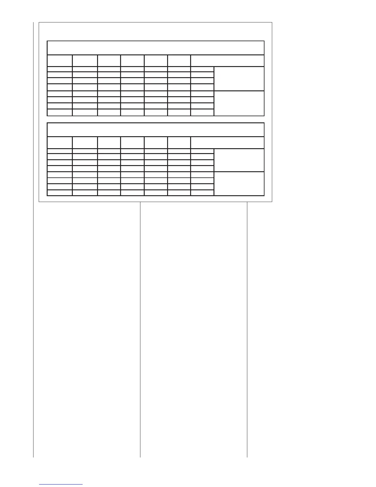
COOLING AIRFLOW SELECTIONS FOR NON-COMMUNICATING CONDENSERS
ON OFF OFF 1200 CFM 600 CFM 1200 CFM 3 Ton A/C
ON OFF ON 1000 CFM 500 CFM 1000 CFM 2.5 Ton
ON ON OFF 800 CFM 400 CFM 800 CFM 2 Ton A/C
ON ON ON 600 CFM 300 CFM 600 CFM
OFF OFF OFF 1200 CFM 900 CFM 1200 CFM 3 Ton A/C
OFF OFF ON 1000 CFM 750 CFM 1000 CFM 2.5 Ton
OFF ON OFF 800 CFM 600 CFM 800 CFM 2 Ton A/C
OFF ON ON 600 CFM 450 CFM 600 CFM
MODULATING FURNACE COOLING AIRFLOW RATES, 1/2 HP (1200 CFM Max) motor settings
(applies only to systems configured with non-communicating condenser).
SW1, Pos. 2 SW1, Pos. 1
YH Single
stage
YL Low 2
stage
YL+YH High 2
stage
Notes
Low Heat Airflow = approx. 50% of
High-Stage Cooling (Could be
used with condensers with two
compressors.)
HIGH SEER (16+) Premium
Cooling airflow (SW1, Position 6 is
ON)
SW2, Pos. 6
ON OFF OFF
2000 CFM 1000 CFM 2000 CFM 5 Ton A/C
ON OFF ON
1600 CFM 800 CFM 1600 CFM 4 Ton A/C
ON ON OFF
1400 CFM 700 CFM 1400 CFM 3.5 Ton
ON ON ON
1200 CFM 600 CFM 1200 CFM 3 Ton
OFF OFF OFF
2000 CFM 1400 CFM 1800 CFM 5 Ton A/C
OFF OFF ON
1600 CFM 1200 CFM 1600 CFM 4 Ton A/C
OFF ON OFF
1275 CFM 1050 CFM 1400 CFM
3.5 Ton
OFF ON ON
1200 CFM 900 CFM 1200 CFM 3 Ton
Low Heat Airflow = approx. 50% of
High-Stage Cooling (Could be
used with condensers with two
compressors.)
HIGH SEER (16+) Premium
Cooling airflow (SW1, Position 6 is
ON)
SW2, Pos. 6
MODULATING FURNACE COOLING AIRFLOW RATES, 1 HP (2000 CFM Max) motor settings
(applies only to systems configured with non-communicating condenser).
SW1, Pos. 2 SW1, Pos. 1
YH Single
stage
YL Low 2
stage
YL+YH High 2
stage
Notes
SW1-4 FAN SPEED SELECT – This
dipswitch is used to select the continu-
ous fan speed when the furnace is con-
figured with a non-communicating ther-
mostat.
“OFF”
½ HP MOTORS = Approx. 600 CFM
1 HP MOTORS = Approx. 1000 CFM
“ON”
½ HP MOTORS = Approx. 1200 CFM
1 HP MOTORS = Approx. 2000 CFM
SW1-3 HEAT RISE ADJUST – This dip-
switch is used to select desired temper-
ature rise in the heating mode. The
heat rise wi
ll always be closer to the tar-
get if the supply air sensor is properly
installed (see sub-section in this section
titled “SA SENSOR” below).
“OFF” will yield the maximum heat rise.
(Target heat rise is 65°F but this value
may vary slightly between low and high
fire. Temp. rise will always be closer to
the target if the “SA SENSOR” is prop-
erly installed.)
“ON” will increase the airflow to yield the
minimum heat rise. (Target heat rise is
55°F but this value may vary slightly
between low and high fire. Temp. rise
will always be closer to the target if the
“SA SENSOR” is properly installed.)
SW1-5 AND SW1-6 – COOLING
AND HEAT-PUMP AIRFLOW
ADJUSTMENT – These dipswitches
are used to adjust the cooling and
heat-pump airflow for non-communi-
cating systems slightly based on the
user’s preference.
SW1-5 = “OFF”, SW1-6
= “OFF” –
No adjustment.
SW1-5 = “ON”, SW1-6 = “OFF” –
+10% adjustment.
SW1-5 = “OFF”, SW1-6 = “ON” – -
10% adjustment.
SW1-5 = “OFF”, SW1-6 = “OFF” –
No adjustment.
 Loading...


