24
2. Adjust the set point several degrees below
(cool mode) or above (heat mode) the room
temperature to assure the thermostat is
calling for operation and will continue to do so
throughout the charging process.
3. When the charging process is complete, adjust
the temperature set-point to the desired level.
5.7 Indoor Air-Flow Verication
Correct indoor air-flow and proper supply air
distribution is critical to system comfort, efficiency
and reliability. Excessive indoor air-flow results in
elevated humidity levels in the cooling mode and
excessive air noise. Low indoor air-flow reduces
system capacity and can result in coil icing and
compressor failure in the cooling mode and can
cause nuisance high pressure switch tripping and
increases power consumption in the heating mode.
Fortunately, when the (-)A18AZ/(-)P18AZ heat pumps
are matched to the correct air-handler or furnace/coil
combination and are controlled by the communication
EcoNet
TM
Control Center, the indoor air-flow is
automatically controlled to the proper level based on
the model data stored in the UODC memory card.
When the indoor blower is operating, the EcoNet
TM
Control Center will display the indoor air-flow in
the Service Menu of the control. The approximate
indoor air-flow is also displayed in 100 CFM [47 l/s]
increments by a flashing LED on the air-handler or
furnace control board while the blower is operating
(one flash per 100 CFM [47 l/s]) for installations
where a conventional 24VAC thermostat is used.
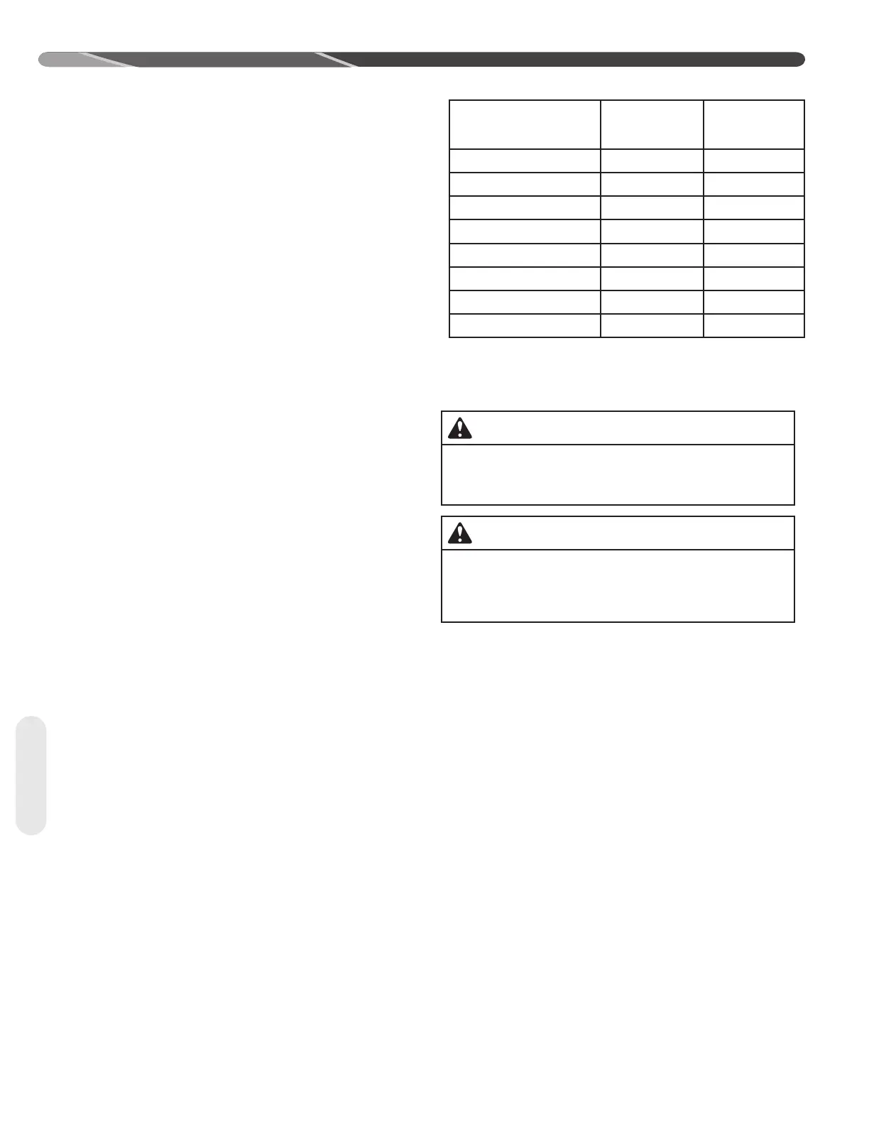
Once the system is operating in the Charging Mode,
confirm the indoor air-flow is close to those values in
the table below. If the displayed indoor air-flow is not
reasonable close to the value in the table, confirm
cooling dehumidification is disabled, the indoor air-
flow trim adjustment is set to 0%, and verify the
model numbers of the indoor and outdoor units are
an approved combination by the manufacturer. Once
the indoor air-flow is verified, the indoor air-flow trim
adjustment may be changed to suit the installation
and should be done prior to final charge adjustment.
NOTICE: AHRI rated indoor air-flow may differ
slightly from values in Table 9.
Start-Up
Table 9: Cooling and Heating CFM Ratings
Outdoor Unit
Model No.
Displayed
Indoor CFM
Cooling Mode
Displayed
Indoor CFM
Heating Mode
(-)P18AZ24 800 800
(-)P18AZ36 1200 1300
(-)P18AZ48 1600 1500
(-)P18AZ60 1700 1800
(-)A18AZ24 840 -
(-)A18AZ36 1210 -
(-)A18AZ48 1565 -
(-)A18AZ60 1725 -
5.8 Refrigerant Charging
The refrigerant charge for all systems should be checked
against the Charging Chart located inside the access
panel cover.
WARNING:
The top of the scroll compressor shell is hot.
Touching the compressor top may result in serious
personal injury.
CAUTION:
R-410A pressures are approximately 60% higher (1.6
times) than R-22 pressures. Use appropriate care
when using this refrigerant. Failure to exercise care
may result in equipment damage or personal injury.
IMPORTANT: Do not operate the compressor without
charge in the system.
Addition of R-410A will raise high-side pressures (liquid
and discharge).
NOTICE: System maintenance is to be performed by a
qualified and certified technician.
The optimum refrigerant charge for any outdoor unit
matched with an indoor coil/air handler is affected by
the application. Therefore, charging data has been
developed to assist the field technician in optimizing the
charge for all mounting configurations (UF – Upflow,
DF – Downflow, LH – Left-Hand Discharge, and RH
– Right-Hand Discharge). Refer to the charging chart
inside the access panel cover on the unit and choose
the appropriate column for the specific application being
installed or serviced. New installations utilizing either an
RCF indoor coil installed on a gas furnace or an RHMV
series air handler in the downflow or horizontal right-
hand discharge may require removal of some refrigerant
since the factory charge could result in an overcharge
condition for short line length applications.
The following method is used for charging systems in
the cooling and heating mode. All steps listed should be
performed to ensure proper charge has been set. For
measuring pressures, the service valve port on the liquid
valve (small valve) and the true service port located
between the two service valves are to be used.