36
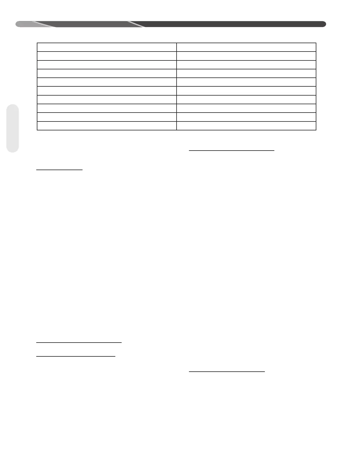
Table 15: EcoNet
TM
Fault Codes & Response Actions (cont.)
EcoNet
TM
Fault Code Response Action
T974_O Line Current Trip 3-strikes to permanent lockout
T981_O Fan Overcurrent Trip 3-strikes to permanent lockout
T982_O Fan Overvoltage Trip 3-strikes to permanent lockout
T983_O Fan Undervoltage Fault 3-strikes to permanent lockout
T984_O Fan Locked Rotor Fault 3-strikes to permanent lockout
T986_O High Refrigerant Pressure Envelope 3-strikes to permanent lockout
T995_O IPM Overcurrent Trip 3-strikes to permanent lockout
T996_O Low Side Overcurrent Trip 3-strikes to permanent lockout
T997_O High Side Overcurrent Trip 3-strikes to permanent lockout
Diagnostics
9.1 Checking Transducers &
Temperature Sensors
TRANSDUCERS:
Checking transducers for accuracy can be tricky.
A technician will be required to do some voltage
reading and math to validate the transducer is
functioning properly. Additionally, comparing it to a
reliable source can also be a challenge. Unless the
gauges have been calibrated recently, the question
remains, which one is right?
Knowing where to take the measurement, and
getting solid reading is crucial. Measurements are
done in the 0-5 volt DC range. One confusing point
may be that we will take our measurements OUT
and IN to the control, which are reversed when we
talk formulas because we want the IN and OUT of
the transducer. For instance, 5VDC out of the control
board, translates to 5VDC into the transducer. And
the lower variable voltage output from the transducer
will be the input to the control board.
The transducer is not removed or disconnected
to make these checks. The technician's meter
leads need to be the smaller needle type, or actual
needles can be used to gain access to the points of
measurements.
Formulas for calculating gauge pressure are shown
below.
SUCTION LINE TRANSDUCER:
PSIG = 375 * (VDC out / VDC in) - 8.1
LIQUID LINE TRANSDUCER:
PSIG = 812.5 * (VDC out / VDC in) - 51.85
IMPORTANT: Do the division inside the parenthesis
first, multiplication second, and subtraction last.
SUCTION LINE TRANSDUCER:
VDC out = 2.4
VDC in = 5.1
So...
PSIG = 375 * (2.4 / 5.1) - 8.1
PSIG = 375 * (0.47) - 8.1
PSIG = 176.25 - 8.1
PSIG = 138.75
LIQUID LINE TRANSDUCER:
VDC out = 3.4
VDC in = 5.1
So...
PSIG = 812.50 * (3.4 / 5.1) - 51.85
PSIG = 812.50 * (0.667) - 51.85
PSIG = 541.67 - 51.85
PSIG = 460.40
The pressures are best measured when the system
is off since they will be the most stable.
The indoor transducer may be removed so the
pressure can be checked with gauges at the actual
port the transducer is connected to. Pressures for
outdoor transducers can be checked at the outdoor
unit service ports with gauges since they are close
enough in proximity to the transducers.
With the system powered, use the smaller meter
tips to measure the voltage at the back of the
transducer harness where it plugs into the control
board. Voltage In will be measured from the Red and
Black wires. (Red is +, Black is -). This should be
very close to 5VDC, but may vary by a few 1/10ths.
Voltage Out will be measured from Green to Black.
(Green is the variable +, Black remains -).
TEMPERATURE SENSORS:
All the temperature sensors/thermistors used in the
equipment use the same scale of 10,000 Ohms at
 Loading...