- 28 -
COMMUNICATION PORTS
On the back of the CPS (see “CPS VIEWS”), the following communication ports are present:
USB connector
Dry contact OUT
Expansion slot for additional communication cards
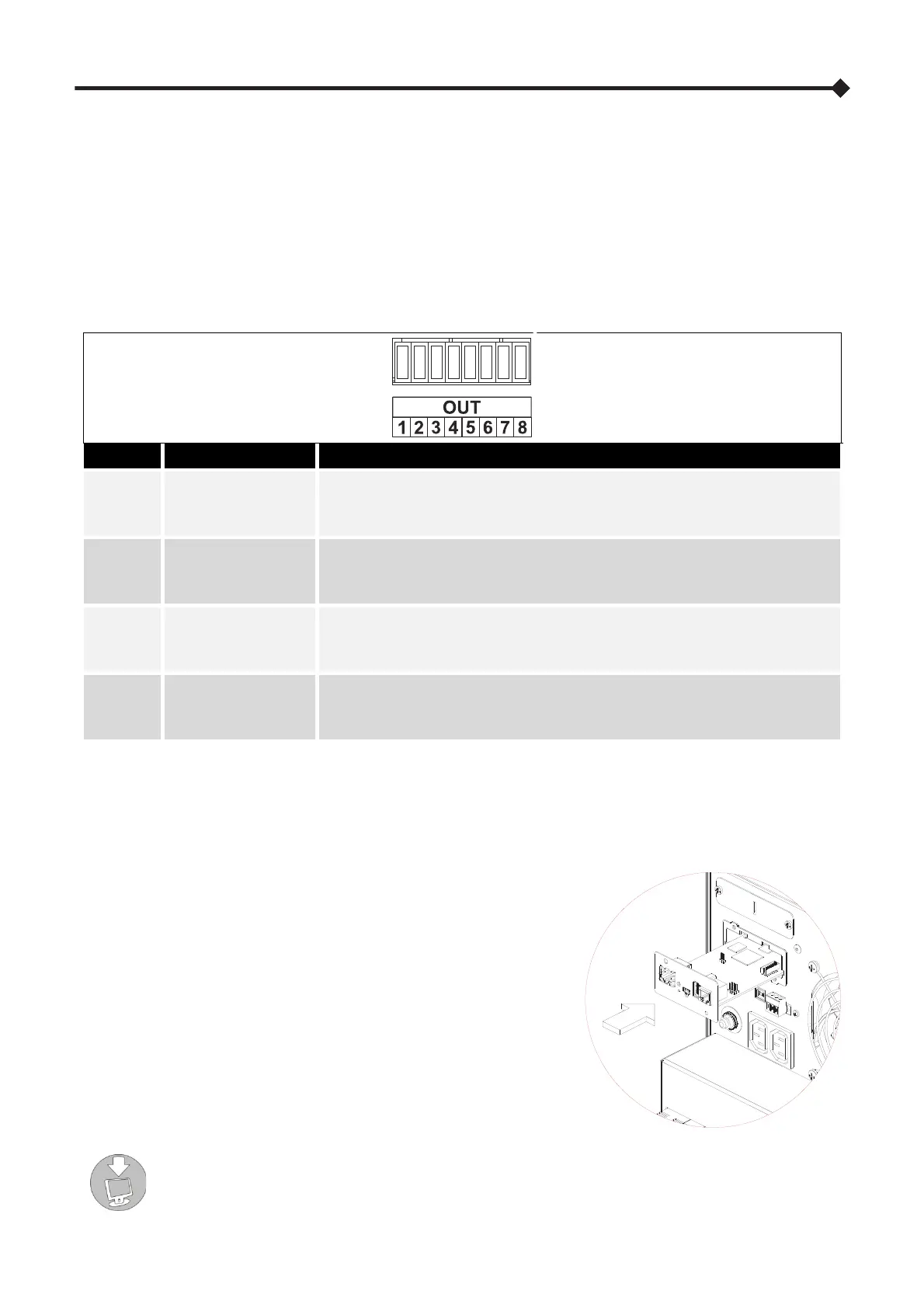
CONFIGURATION FOR OUTPUT SIGNALS (FACTORY DEFAULT)
The table lists the default configurations for the output signals.
OUTPUT FUNCTION DESCRIPTION
OUT 1 Battery working
N.O. contact between pin 7 and pin 8
(If the contact is closed, the CPS system is on battery)
OUT 2 Battery low (*)
Double throw contact: N.O. between pin 6 and pin 8; N.C. between pin 5 and pin 8
(If the contact between pin 6 and pin 8 is closed, the battery is at the end of
discharge)
OUT 3 Battery circuit alarm
N.C. contact between pin 3 and pin 4
(If the contact is open, at least one anomaly or fault is active in the charger stage
or in the batteries)
OUT 4 Normal operation
Double throw contact: N.O. between pin 2 and pin 4; N.C. between pin 1 and pin 4
(If the contact between pin 6 and pin 8 is closed, the CPS system is working)
(*) Double throw contact configurable via the configuration software
NOTE: The output dry contacts are rated to 1A @ 24Vdc or 1A @ 30Vac
COMMUNICATION SLOT
The CPS is equipped with an expansion slot for optional communication
cards (see figure on right) which allows the device to communicate using
the main communication standards.
Some examples:
Serial duplicator
Ethernet network card with TCP/IP, HTTP, HTTPS and SNMP
protocols
JBUS / MODBUS protocol converter card
PROFIBUS protocol converter card
Card with relay isolated contacts
To check the availability of other accessories, visit the website www.riello-ups.com.
 Loading...